Welding Technique and Equipment
SUBMERGED ARC WELDING. In this process, too, heat is supplied by an electric arc and a consumable electrode is used. In this technique, however, a granular flux composed of silicates and other elements is deposited on the weld joint. The arc melts some of the flux and is submerged in the liquid slag that is produced by this melting. The electrode in this method is wire that is fed continuously to the weld joint. High currents used in this technique allow the weld to penetrate deeper below the surface of the pipe than is possible with other welding processes.
GAS-METAL ARC WELDING. This process also uses the heat from an electric arc. The arc is covered by an inert gas, such as argon or helium. The insert-gas-shielded metal arc process uses a consumable, continuous electrode. Since this process requires no flux, no slag is produced on top of the weld. Gas for shielding is delivered to the weld area through a tube; the electrode is fed down through a guide within the tube. Gas metal arc welding (GMAW) is particularly applicable to welding difficult metals and alloys that are susceptible to contamination from the atmosphere,and porosity.Carbon dioxide welding is similar to gas-metal arc welding except that CO2 is used as a shielding gas.
GAS-TUNGSTEN ARC WELDING. An inert gas shield is required when welding with tungsten electrodes using the gas-tungsten arc welding (GTAW) process. This process is particularly suited to welding thin material and to depositing the first weld bead (root pass) because penetration can be controlled more easily than with other welding processes. Good heat control is possible with this process, and it is possible to weld with or without filler metal. The nonconsumable electrodes are not deposited as part of the weld metal. The steel being welded is melted, and the electrode serves only as one pole of the electrical circuit. In some processes, however, a filler wire can be fed into the weld joint if additional metal is needed to fill the joint. There are other arc welding processes:
1. Plasma arc welding, in which a plasma is produced by the heat of a constricted arc/gas mixture. This type of welding is similar to tungsten arc welding since an inert gas is used, but plasma.arc welding's constricting orifice is unique. Plasma/metal-inert-gas(MIG) welding combines the features of plasma arc and inert-gas metal arc processes and permits deep penetration when welding thick material or higher speeds when welding thinner material.
|
|
|
2. Flux-cored arc welding, which is similar to submerged arc and shielded metal arc welding, except the flux is contained in a metal sheath instead of on the wire.
3. Electroslag welding, which is begun much as conventional submerged arc welding. When a layer of hot molten slag is formed, arc action stops and current passes from the electrode to the work through the slag. Heat generated by the resistance to current through the slag fuses the edges of the work pieces.
ELECTRON BEAM WELDING. Though not common in pipeline welding, the electron beam process could have application in proposed laying techniques for installing offshore pipelines in very deep water. The J-curve pipelay method, discussed in Chapter 7, involves lowering pipe from near vertical rather than in a horizontal S-shaped configuration used in conventional offshore pipelaying.
In the electron beam welding process, coalescence is obtained by concentrating a beam composed primarily of high-velocity electrons impinging on the surfaces to be joined. Electrons accelerated by an electric field to extremely high speeds and focused to a sharp beam by electrostatic or electromagnetic fields provide heat for welding. Because the J-curve pipelay technique requires welding to be done at a single station rather than the several stations common on a conventional lay barge, electron beam welding offers an advantage. It is quicker than other methods and can weld thick-wall pipe in a single pass. The process also requires no preheating or postheating of the weld area. In tests on 24-in. pipe with a wall thickness of 1.2 in., complete welds were made in less than 3 minutes. Conventional welding of a joint in the same pipe would require 1 V hours.
Accurate positioning of the beam is important in the electron beam process, and a vacuum must be maintained in the chamber around the pipe. The beam must be concentrated on a spot about 1 mm in diameter, and tolerances are critical.
Welding Procedures and Equipment
Most welding processes can be used with either of the two general types of welding procedures: manual or automated. Of all of the oil and gas pipeline welding done, the bulk is done by manual welding procedures. In manual welding, the welder holds the electrode. He must be highly skilled at maintaining the proper distance between the electrode and the pipe and in moving the electrode along the weld seam at the proper rate. Automated welding equipment also requires skilled operators, but it is easier to obtain consistent, uniform welds because the welding electrode is moved mechanically at the desired distance from the seam and at the optimum speed.
|
|
|
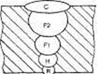
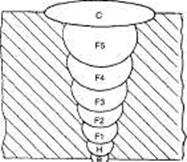
Weld passes. Whether done by manual or automated welding, each pipeline circumferential, or girth, weld usually is completed by making several passes around the circumference of the pipe at the seam between the two joints. The number of passes, or beads, depends on the thickness of the pipe wall and the welding procedure. Regardless of pipe wall thickness, however, a typical pipe weld consists of a root pass (the first pass made around the seam), a hot pass applied over the root pass, several fill passes (which fill in the space between the pipe ends), and a cap pass.
The root pass is especially critical. An improperly applied root pass can burn through the pipe wall, producing a defective weld that will cause the weld to be rejected when inspected. Since the root pass initially joins the two lengths of pipe, it is necessary that they be correctly aligned and spaced before welding begins. In some procedures, the root pass is deposited from inside the pipe; then all other weld passes are made from the outside of the pipe. In other cases, the root pass is made from the outside of the pipe. If a metal slag is produced during welding, it must be removed before the next weld pass is made.
Following the root pass, the hot pass is deposited. It is normally made before the root pass bead cools completely. The hot pass is also critical to overall weld quality. After it is made, the hot pass is cleaned of slag, if necessary, before fill pass welding begins.
After the hot pass, the required number of fill passes is made. Fill passes build up the weld and fill in the seam between the two pipe joints with weld metal. The number of fill passes required depends primarily on the wall thickness of the pipe being welded. It also may depend on the particular welding procedure being used. Thin-wall pipe may only require one fill pass, while the number of passes may be five or more for pipe with a thicker wall. The speed with which pipeline welds can be made depends heavily on the number of fill passes required, in addition to the outside diameter of the pipe. A welder can deposit a certain amount of weld material in a specified time. If a number of passes are made on the same weld seam, fewer complete welds can be made per day. The amount of weld material that must be deposited also increases as the pipe diameter increases, so fewer welds can be made in a day on large-diameter pipe.
|
|
|
The final weld is the cap pass. It is normally wider than the last fill pass, and weld metal is not deposited in as thick a layer as is the case with the other weld passes. The top of the cap pass extends slightly above the pipe exterior.
Fig. shows examples of the weld passes required in a pipeline girth weld.
| ||||
| ||||
 Detail 4-4 fill passes
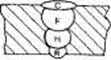 Ft = root pass (internal) H = hot pass F = fill pass С = cap pass
Detail 1-1 fill pass
Ft = root pass (internal) H = hot pass F = fill pass С = cap pass
Detail 1-1 fill pass
| |||
| |||
 Detail 2-2 fill passes
 Detail 5-5 fill passes
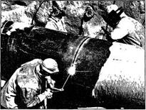
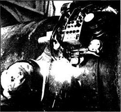
MANUAL WELDING. The largest share of oil and gas pipeline welding is still done manually (Figure 8-2). Welders along the pipeline right of way use vehicle-mounted welding machines and weld the individual joints of pipe together alongside the pipeline ditch. The number of welders on a pipeline job depends on the length of the pipeline, the diameter and wall thickness of the pipe, and other factors.
|
|
|
Typically, one welder applies the root pass, another welder the hot pass, one or more welders the fill passes, and another welder the cap pass.
Manual pipeline welding not only requires great skill, but also involves conditions that are often difficult and unpleasant. Since the pipe seam must be welded completely around the circumference of the pipe with the pipe in a horizontal position, the welder must be down on the ground in an uncomfortable position to complete the weld on the lower portion of the pipe. In extreme weather, it is often necessary to provide a shelter or enclosure for the welder to protect against wind, blowing dirt or sand, and cold. Not only is this needed for the welder's comfort, but blowing dirt, moisture, and high wind can reduce weld quality. Some welding shelters include wooden floors, doors, exhaust vents, lighting, and heating to provide properly controlled welding conditions. Other shelters consist only of a canvas hood over the welder and the joint being welded.
AUTOMATIC WELDING. In the late 1960s, automated welding equipment reached the commercial development stage. Since that time, it has been used in pipeline welding in many parts of the world for a wide range of pipe sizes. It is used both for land pipeline construction and, on lay barges, for offshore pipeline construction.
These advantages of automated welding systems have been cited:
· Increased weld metal deposition rate
· Reduced volume of weld metal
· Improved consistency of weld strength, toughness, and
radiographic quality
· Reduced vulnerability of weld quality to human error
· Reduced physical strain on the welder/operator
· Ease of training operators
· Reduced manpower and equipment requirements for heavy wall and large-diameter pipe
In automated welding, as in manual welding, a root pass, hot pass, fill passes, and cap pass are required. A continuous wire is used to supply the weld metal to be deposited.
The CRC automated welding system in use in the early 1980s, for example, featured a fine-wire, gas-metal arc welding system consisting of three major components: a pipe end facing machine, a combination internal welder/line-up clamp, and an external welding carriage.
The pipe facing machine served a special purpose. Line pipe is usually manufactured and delivered with the ends bevelled at a standard 30°. For automated welding, a modified bevel was found to increase the quality of the weld, and the facing machine was used to modify the standard 30° bevel in the field to prepare for automated welding. The facing machine included a clamp section and a machining section. The clamp section secured the pipe. Cutting tools mounted on a rotating face plate then machined the end of the pipe to the desired bevel. The pipe facing machine typically was suspended from a sideboom tractor, and the facing operation normally required 2-5 minutes.
The internal line-up clamp/welder positioned inside the pipe aligns the two pipe ends, locks them in place, then automatically welds the root pass on the inside of the pipe. The welding section of the unit has four welding heads for pipe diameters from 24 in. to 38 in. and six heads for 40-in. to 60-in. diameter pipe. The heads are mounted around a ring gear driven by an electric motor. A four-head machine, for example, begins welding with two heads at the 12 and 3 o'clock positions as seen from the open end of the pipe. These heads weld downhill to 3 and 6 o'clock, respectively, typically at about 30 in./min. The other two heads move into position at 12 and 9 o'clock, and when the first two heads are finished, the second two weld from 12 to 9 o'clock and from 9 to 6 o'clock, respectively. When the root pass bead is complete, the clamps are removed and the unit propels itself through the pipe joint just welded and stops automatically at the open end.

Pipeline Corrosion
Corrosion is deterioration of intrinsic properties in a material due to reactions with its environment. It is the oxidation of metals reacting with water or oxygen. Weakening of iron due to oxidation of the iron atoms is a well-known example of electrochemical corrosion. This is commonly known as rust. This type of damage usually affects metallic materials, and typically produces oxide(s) and/or salt(s) of the original metal. Corrosion also includes the dissolution of ceramic materials and can refer to discoloration and weakening of polymers by the sun's ultraviolet light.
Most structural alloys corrode merely from exposure to moisture in the air, but the process can be strongly affected by exposure to certain substances. Corrosion can be concentrated locally to form a pit or crack, or it can extend across a wide area to produce general deterioration. While some efforts to reduce corrosion merely redirect the damage into less visible, less predictable forms, controlled corrosion treatments such as passivation and chromate-conversion will increase a material's corrosion resistance.
Corrosive substances
A corrosive is a chemical, solid, liquid, or gas, capable of irreparably harming living tissues or damaging material on contact. Corrosive chemicals include the following classes:
· Acids
· Bases ("caustics" or "alkalis")
· Dehydrating agents such as phosphorous pentoxide and calcium oxide
· Halogens and halogen salts such as bromine, iodine, zinc chloride, and sodium hypochlorite
· Organic halides and organic acid halides such as acetyl chloride and benzyl chloroformate
· Acid anhydrides
· Some organic materials such as phenol ("carbolic acid").
Дата добавления: 2019-01-14; просмотров: 141; Мы поможем в написании вашей работы! |

Мы поможем в написании ваших работ!