General Characteristics of Pipe Flow
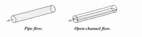
Although not all conduits used to transport fluid from one location to another are round in cross section. These include typical water pipes, hydraulic hoses and other conduits that are designed to withstand a considerable pressure difference. There are two situations where one pipe is completely filled with the fluid being transported (pipe flow) and one through which rainwater flows without completely filling the pipe (open-channel flow). The difference between open-channel flow and pipe flow is in the fundamental mechanism that drives the flow. For open-channel flow, gravity alone is the driving force. For pipe flow, gravity may be important, but the main driving force is likely to be a pressure gradient along the pipe.
Laminar or Turbulent Flow
The flow of a fluid in a pipe may be laminar or turbulent. The distinction between laminar and turbulent pipe flow was first pointed out by Osborne Reynolds (1883). The actual transition or turbulent flow may take place at various Reynolds numbers, depending on how much the flow is disturbed by vibrations of the pipe, roughness of the entrance region, etc.

The region of flow near where the fluid enters the pipe is the entrance region. A boundary layer is produced along the pipe wall so that the initial velocity profile changes with distance along the pipe, until the fluid reaches the end of the entrance length. The flow in long, straight constant diameter sections of a pipe becomes fully developed, i.e. the velocity profile is the same at any cross section of the pipe. The details of velocity profile are different for laminar and turbulent flows. The nature of the pipe flow is strongly dependent on whether the flow is laminar or turbulent. This is a direct consequence of the differences in the nature of shear stress in laminar and turbulent flows. The shear stress in laminar flow is a direct result of momentum transfer among the randomly moving molecules. The shear stress in turbulent flow is largely a result of momentum transfer among the randomly moving molecules, finite-sized bundles of fluid particles.

Fig. Entrance region, developing flow, and fully developed flow in a pipe system
Turbomachines and Their Characteristics
Turbomachines are classified as axial-flow, mixed-flow or radial-flow machines depending on the predominant direction of the fluid motion relative to the rotor’s axis as the fluid passes the blades. For an axial-flow machine the fluid maintains a significant axial-flow direction component from the inlet to the outlet of the rotor. For a radial-flow machine the flow across the blades involves a substantial radial-flow component at the rotor inlet, exit or both. In other machines, called mixed-flow machines, there may be significant radial-flow and axial-flow velocity components for the flow through the rotor row. Each type of machine has advantages and disadvantages for different applications and in terms of fluid-mechanical performance.

Fig. Radial-flow turbomachine

Fig. Axial-flow turbomachine
Performance characteristics and operating speed are usually given in the form of a pump performance curve (commonly referred to as capacity). Pump performance characteristics are also presented in charts. Since impellers with different diameters may be used, performance characteristics for several impeller diameters can be provided with corresponding lines of constant efficiency and brake horsepower. An additional curve is given, labeled NPSH which means net positive suction head. The significance of this curve is related to conditions on the suction side of the pump, which must also be carefully considered when selecting and positioning a pump.
Centrifugal pumps are radial-flow machines that operate most efficiently for applications requiring high heads at relatively low flow-rates. In mixed-flow pups and axial-flow pumps, the specific speed increases, the head decreases, the speed increases, the impeller diameter decreases and the eye diameter increases.

Fig. Schematic diagram of basic elements of a centrifugal pump
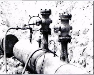
Valves are mechanical devices that are installed in pipelines to control flow or pressure. Valves are an important part of piping systems and if not properly selected and operated, they can cause operation problems. The primary valve types, classified by their function, are:
· control valves – used to control flow, pressure, liquid level, cavitation and pressure transients;
· isolation (block) valves – placed on each side of control valves and pumps, allowing them to be removed for repair or replacement;
· check valves – used to prevent reverse flow;
· relief valves – admit air to the pipe while he pipe is being drained to prevent excessive vacuum pressures and reduce the possibility of collapsing thin-walled pipes;
· air valves- designed to expel large amounts of air at low pressure during filling and release small amounts of pressurized air during operation.
| Air valve | Воздуховыпускной клапан |
| Axial-flow machine | Осевые гидравлические машины |
| Boundary layer | Граничный слой |
| Cavitation | кавитация |
| Check valve | Обратный клапан |
| Conduit | Трубопровод; труба |
| Control characteristics | Характеристика регулирования |
| Control valve | Распределительный клапан |
| Cross section | Поперечное сечение |
| Developing flow | Развивающийся поток |
| Driving force | Движущая сила |
| Duct | Труба (не с круглым поперечным сечением) |
| Entrance region | Входной участок |
| Flow control valve | Дроссель, регулятор потока |
| Flowrate | Дебит \ скорость потока |
| Fluid motion | Движение флюидов |
| Fully developed flow | Развитый поток |
| Head loss | Потеря напора |
| Impeller | крыльчатка |
| Isolation (block) valve | Стопорный (запорный) клапан |
| Laminar flow | Ламинарный поток |
| Loss | потеря |
| Mixed-flow machine | Диагональные гидравлические машины |
| NPSH(net positive suction head) | Кавитационный запас |
| Open-channel flow | Поток (в не полностью заполненной трубе) |
| Performance characteristics | Рабочие характеристики |
| Performance curve | Кривая КПД |
| Pipe flow | Поток в трубопроводе |
| Pipe system | Система трубопроводных линий |
| Pressure drop | Падение давления |
| Pump capacity | Подача насоса |
| Pump head | Напор насоса |
| Pump speed | Скорость работы насоса |
| Radial –flow machine | Радиальные машины |
| Relief valve | Перепускной клапан |
| Reverse flow | Обратный поток |
| Shear stress | Напряжение сдвига |
| Specific speed | Удельное число оборотов быстроходность (насоса) |
| Turbomachine | турбомашина |
| Turbulent flow | Турбулентный поток |
| Velocity profile | Скоростной профиль |

Pipeline Construction
In the petroleum industry, pipelines are used for a variety of purposes:
- gathering crude oil from individual leases and delivering it to a central location for processing;
- transporting crude oil from fields to port terminals for tanker transportation;
- moving crude oil from processing centers and supply points to the refineries and other markets;
- moving gas from fields to gas processing plants and from these plants to markets;
- distributing petroleum products from the refineries to the distribution centers.

| gathering system | система нефтесбора |
| pump station | насосная станция |
| crude trunkline | магистральный трубопровод |
| crude tank farm | резервуарный парк \ нефтебаза |
| tanker | танкер |
| marine terminal | портовая нефтебаза |
| refinery | НПЗ –нефтеперегонный завод |
| petrochemical plant | нефтехимический завод |
| product line | продуктопровод |
| processing | переработка |
| distribution center | распределительная база |
| oil tankage | нефтехранилище |
| destination | пункт назначения |
Pipeline Components
A pipeline system is comprised of the following components:
- line pipe – the main component of every pipeline and is usually metallic (carbon steel \ corrosion resistant alloy);
- pig traps – allow safe loading, launching, receiving and retrieval of pigs without disrupting the fluid in the pipelines;
- block valve stations – isolate section of the pipeline and limit the release of line contents in case of a leak or pipeline rupture;
- emergency shut-down valves (ESD) – located at both ends of the pipeline and enable automatic shut down of the line in case of an emergency;
- slug catcher – installed at the end of a multi-phase pipeline to prevent slugs and to ensure a constant gas flow into the receiving station;
- cathodic protection system – installed as a backup to the external coating to prevent corrosion of the external surface of the pipelines;
- pressure protection system - protects a pipeline when the line pressure exceeds the max. allowable pressure;
- telemetry system – permits pipeline monitoring and remote operation from a central location;
- leak detection system – installed to warn that a leak occurred.

| line pipe | труба |
| pig trap | Узел запуска \ приема скребка |
| block valve station | Аварийный клапан для отключения |
| ESD (emergency shut-down valve) | Аварийный клапан для временного прекращения |
| slug catcher | Ловушка для конденсата |
| cathodic protection system | Система катодной защиты |
| pressure protection system | Система защиты от избыточного давления |
| telemetry system | Система телеметрии |
| leak detection system | Система определения утечек |
| corrosion resistant | коррозионноустойчивый |
| launching | Запуск |
| retrieval | извлечение |
| receiving | прием |
| loading | |
| disrupt (ing) | |
| rupture | Порыв, образование трещин |
| shut down | Временное прекращение |
| emergency | |
| leak | утечка |
| slug | пробка |
| receiving station | |
| backup | Резервное устройство |
| coating | Защитное покрытие |
| allowable pressure | |
| exceed | |
| monitoring | |
| remote operation | |
| warn | |
| install |
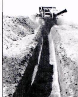
Land Pipeline Construction
- Survey, setting out (разведка , установка) – marking the centerline of the pipeline ditch and edges of the right-of-way.
- Right-of-way (ROW), clearing, grading (полоса отчуждения, расчищение , грединг) – ROW width is determined by the diameter of the pipeline to be installed and includes room for the pipeline and working space for the construction equipment used to install the pipeline. A low silt fence protects it against erosion.
- Ditching (установка \ прокладывание траншей) – excavated soil (spoil) is deposited on the ditch bank. In certain areas, particularly farmland, the ditch will be excavated in two passes with a first pass removing topsoil and the second pass excavating the remaining soil to the required pipeline burial depth.
- Stringing (укладка плетей трубопровода) – laying sections of pipe along the ROW (stringing) uses pipe in varying lengths (joints). Stringing trucks transport pipe from a stockpile to the ROW where a pipe layer (sideboom) or crane lays them along the ROW.
- Bending (сгибание труб) – joints of pipes can be bent to accommodate elevation changes, horizontal direction changes or both along the ROW. If a change cannot be designed within the filed-bending constraints, special pipe bends (factory bends, hot bends) must be manufactured for the special location.
- Road crossing (пересечение дорог) – boring beneath a road does not damage the road surface, and traffic flow is not interrupted by the boring activity. Line pipe used for the road crossing has a thicker external coating to provide extra protection during installation. The road crossing pipe is joined to the welded strings of line pipe by a tie-in-crew using manual welding.
- Skidding (опорная рама для сварки трубопровода) – the pipe: before being welded, line pipe is lifted onto skids made of timber and stockpiles along the ROW so that the entire circumference is accessible.
- Welding (сварка) – the work here assumes use of automatic welding to join the sections of line pipe, which provides consistency, uniform welds and fewer repairs. To prepare the line pipe for automatic welding, a beveling and facing machine trims, cuts and grinds the pipe ends with the special edge preparation required by the process. Line pipe comes from the pipe mill with a standard edge preparation or with a plain end if the pipe is specially ordered for automatic welding.
- Line-up, internal welding (центровка , внутренняя сварка) – a series of pneumatically operated pistons radially spaced around the internal clamp centers the joints and correctly aligns the pipe ends for welding. The fist welding pass is made with the internal welding torches and is called the “root”; this is the primary strength weld that fuses the two pipes.
- External welding (firing line back end) (наружная сварка \ ) – the external torches make the next welding pass (hot pass). Together the root and hot passes provide the required fusion and strength to join the pipes permanently. The remainder of the weld passes (fill passes) is made from the outside. The final welding pass (cap) completes the weld and forms a cap over the bevel. The number of welding stations for the automatic welding crew varies depending upon the wall thickness of the line pipe.
- Horizontal directional drilling (HDD) () – is often the preferred method for constructing the pipeline across such obstacles as streams or wetlands. On a typical river crossing – on the near side (rig side), the trailer-mounted drilling rig is positioned near an excavation filled with water to contain and settle the spoil or cuttings that result from he operation. The tanks hold a mixture of drilling mud and water that is pumped into the hole, lubricating the drillstring. The drillstring, sections of pipe that make the hole, contain a survey instrument near the head or cutting ed. Operators on the drilling rig electronically control the instrument to guide the cutting head in both vertical and horizontal directions. The drill moves to the opposite bank under the bottom of the river and deep enough to protect the pipeline from future river-bottom changes. This first drill forms the “pilot” hole. With drill pipe through to the far side (pipe side), crews attach a reaming device to enlarge the pilot hole to accommodate the line pipe. The rig reverses to pull the reamer back, cutting and enlarging the opening. This operation is called “pre-reaming”. Drill pipe is attached to the far side of the reamer so that it can be pulled back from the near side, once the pre-reaming operation is complete. The line pipe string to be installed has been welded; NDT inspected, tested and is supported by steel cradles that incorporate rollers, allowing the line pipe string to slide. This string of pipe may be very long, depending on the width of the crossing. Multiple strings may be required for the widest crossings and when the first string has been nearly pulled through the crossing, the next string will be lifted and placed on the cradles and manually welded to the last pipe in the first string. For installing the line pipe, a cap incorporating a swivel joint is connected to the leading end of the pipe string. The swivel joint is connected to the reamer and the drilling rig again pulls the reamer back through the hole from the pipe side to the rig side, along with the pipe string connected to the reamer. This final operation is the pull=back and installs the line pipe under the river.
- Non-destructive testing (NDT) () – after welding the joints are inspected by non-destructive methods to verify weld integrity. How many welds are inspected varies depending on the code to which the pipeline is designed, the service of the pipeline (gas or oil products), its location (environmentally sensitive areas, highly populated areas or other risk factors) and the requirements of the pipeline owner. Inspection of 100% of the welds is not uncommon. Customary inspection is by internal X-ray, external gamma ray or ultrasonics.
- Field-joint-coating ( ) – the factory-applied external coating does not cover a few inches of each pipe to allow for welding. After NDT inspection, field-joint coating is applied to the bare sections at he pipe welds covering the exposed pipe and the weld.
- Padding, lowering and backfilling (присыпка , спуск трубопровода в траншею , засыпка траншей трубопровода) – welded strings of pipe vary in length depending on the terrain conditions but are typically hundreds of feet long. Before the pipe strings are lowered into the ditch, selected padding, usually sand, is placed on the ditch bottom to cushion the pipe. In rocky soil, the fill may be placed around and on top of the pipe (shading). A fleet of sidebooms lifts the string off the timber skids and lowers it into the ditch. The sidebooms use special slings that cradle the pipe on rollers allowing the sideboom to travel down the ROW as the pipe slides into the ditch. The ditch spoil is pushed back into the ditch to cover the pipe except for certain sections that must be left uncovered to make tie-in welds and allow for hydrostatic testing.
- Tie-in welding (соединение секции) – individual pipe string ends are cut and trimmed to join the pipe strings with external clamps accurately aligning the pipe. NDT inspection is performed after the pipe has been welded and the field-joint coating applied. Tie-in welding is also required at road crossings, river crossings and other intersections along the ROW where the main production welding crew cannot access the pipe.
- Hydrostatic testing, final tie-in (опрессовка , последнее соединение секции ) – the pipeline is filled with water until the internal pressure in the pipeline exceeds the internal pressure to which the line will be subject during operation. The elevation profile of the pipeline determines the lengths of the hydrostatic test sections because elevation changes affect the internal pressure. Water for hydrostatic testing is typically taken from rivers and lakes along RO. Dry areas may require a well to be drilled or water to be delivered by truck along the ROW. After sections have been hydrostatically tested, they are joined with a manual tie-in weld. These final welds are NDT inspected. After hydrostatic testing and final tie-in, open sections of the ditch are filled in.
- Final clean-up, ROW restoration (восстановление) – grading the ROW smooth and clear, placing marker signs to identify the pipeline location, repairing any fences or other structures temporarily removed for construction and seeding the soil to reintroduce vegetation are the final activities. Special attention is paid to drainage and erosion control so that ROW, with time, is restored as closely as possible to its pre-construction while allowing access for regular visual inspections.

Right-of-way (ROW)
Trenching

Stringing and bending

Pipeline coating

Backfilling \ clean-up

Special construction considerations

Horizontal drilling
Testing
 Joining Pipes
Piping refers to the overall network of pipes, fittings, flanges, valves and other components that comprise a conduit system to convey liquids. Whether a piping system is used to convey fluids from one point to another or to process and condition the fluid, piping connections serve an important role in the operation of the system.
Pipes can conduit fluid under gravity, vacuum, low-pressure, or high pressure in a process, pneumatic or hydraulic system. Depending on the application, pipe connections can take a variety of forms.
Pipe and fittings are produced in a wide range of materials including: ductile or cast iron, malleable iron, brass, copper, cast steel, plastic and fiberglass. Pipe joints can be permanent or mechanically joined, allowing disconnection. Permanent joints involve welding or crimping metal pipe and cementing plastic pipe. Joints that can be taken apart include threaded, flanged and coupled designs. Flanges can be loose, threaded or welded to pipe ends and are used on metal and plastic pipe.
Threaded
Threading is one of the most popular and least expensive methods of joining steel pipes. The tapered male fitting is forced into the tapered female fitting. Yielding metal creates a seal. Threads other than taper pipe threads can be used for piping connections where tightness of the joint depends on a seal weld or seating surface other than the threads. While threaded joints can be dismantled, it is preferable to use unions. Threaded pipe is available in sizes from 1\16 to 24 in.
Welded
Welded joints are commonly used with steel pipe because these joints are stronger and less prone to leakage than threaded and flanged joints. Also, this method does not add weight to the piping system as flanges do or require a pipe wall thick enough to be threaded.
Pipe up to 2-in. size is generally socket-fitting, fillet welded. Larger pipe 3-36 in, is usually butt welded. The most common joint is the circumferential butt joint. During the welding procedure, to avoid entrance of welding material into the pipe, backing rings may be used.
Soldered
A soldered joint is a rigid, pressure-type joint made with a filter metal that, when heated to its melting point, is drawn into the annular space between pipes and fitting by capillary action. This type of joint is generally limited to pipe up to 8 in. because of the difficulty of applying heat evenly to the joint. Brazing is similar to soldering except higher heat is required for the filler metal. It is used where higher pressure ratings are required.
Compression
Compression couplings usually can be used with all types of pipe and do not require any pipe preparation. They consist of an inner elastometric gasket and an outer metallic sleeve with integral bolts for compressing the gasket. They are available for pipe up to 144-in. OD.
Crimped or grooved
The use of mechanical joints in piping systems is becoming popular. A crimped joint is designed to join light-wall steel and copper pipe, metallic or nonmetallic that is capable of being cut or roll grooved up to 2-in.
Cemented
Solvent joining can be used on vinyl pipe and some others, available up to 12-in. Polyolefin and other pipes require heat fusion and are available up to 6-i. Fibreglass pipe requires an adhesive, resin impregnated fabric or threads to make a joint. It is readily available in sizes from 1\2 to 144-in.

Welding Processes
In a broad sense welding is a metal-joining process wherein coalescence is produced by heating to suitable temperatures with or without the use of filler metal. The sources of heat for welding include electric arc, electric resistance, flame, laser, and electron beam. The first three are traditional methods; laser and electron beam welding are relatively recent developments. Most processes used in field pipeline welding use a filler metal, do not involve the application of pressure, and depend on an electric arc for the heat source.
Дата добавления: 2019-01-14; просмотров: 252; Мы поможем в написании вашей работы! |

Мы поможем в написании ваших работ!