Creating solid models with extrude.
The creation of a model of a wooden wardrobe.
The algorithm works as follows:
1. Using Polyline draw a rectangle with sides 800х200 mm. Then use Extrude extrude it on 16 mm.Using the Copy command, we get the shelf and up the cabinet (Fig. 7.1)

Fig. 7.1 Creating horizontal cabinet elements.
2. Using the Polyline command, draw a rectangle with sides 200x16 mm to the side of the cabinet base. Then, using the Extrude command, squeeze it out 750 mm, getting the right vertical part of the cabinet. Using the Copy command, we get the left vertical part of the cabinet. And then turning the cabinet, we similarly draw the back panel of the cabinet.
3. Select the View tab and the Material Browser item. We select wood - pine for the cabinet elements, and plywood for the back panel (Fig. 7.2a). The final cabinet view with Realistic visualization is presented (7.2b)

Fig. 7.2a. Address to the Browser of materials.

Fig. 7.2b. Realistic cabinet visualization.
Similarly, using the Extrude command, a nut is created (Fig. 7.3)

Fig. 7.3. Examples of extrusion models
Laboratory work.
Creating Solid State Cross Section Models
For this, several sections of the future body are created (circles, polygons, ellipses and other closed objects act as sections).
Objects are placed vertically one above the other. Then the Loft command is used (Fig. 7.4) 
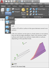
Fig. 7.4. Examples of obtaining cross-sectional models
Laboratory work
Creation of solid models by rotation.
By means of two-dimensional constructions, 1/4 of the contour of the future figure and the vertical and horizontal axes of rotation are specified. We use the standard procedure Mirror relative to the horizontal axis and get half the future pulley. Then, using the Rotate command and selecting the vertical axis, we get an image of a pulley (Fig. 7.5).


Fig. 7.5. Examples of obtaining models by rotation
Laboratory work.
Creation of solid models by shift.
As an example, create a screw. To begin with, a “frame” is created - a spiral (helicoid). For it, the radius, the number of turns, the height of the spiral are set. Then, a “winding” profile (usually in a perpendicular plane) is created at either end of the spiral. It can be a circle, triangle, rectangle, etc. Using the three-dimensional Shift command, we get a “winding”. It remains to add a coaxial cylinder and the screw is ready (Fig. 7.6).
|
|
|


Fig. 7.6. Examples of obtaining models by shear
Laboratory work.
Parametric design
In the tape interface in the workspace, we find the Parameterization tab (Fig. 8.1)

Fig.8.1 Appeal to parameterization in the tape interface
Consider the paragraph drop-down menus PARAMETERIZATION.
Parametric design is intended to ensure that any relationships or constraints whose fulfillment makes it simple to build parts. At various rebuilds of objects geometrical dependence confirm its functionality.
Thus, the geometrical constraints is designed to provide a constant geometric arrangement of certain objects and they are specified for specific points of objects, katariinanlaakso points based on (constraint point) or the objects themselves.
Different objects have points according to different locations:
- line - point relation can act as an endpoint and midpoint of a line;
- arc - as of the points of dependence can be the center of the arc, chechnyatoday arc and its mid;
the circle as a point of dependence can ispolzovatsya circumference;
- the ellipse - the point of dependence can be used centralops;
-polyline - end and mid-points lineinymi arcuate segments and arcuate segments;
- spline - only endpoints can act as points of dependence;
block, external link, text, multi-text attribute, the table - all of these objects as a point of dependence can mettalica the base insertion point.
To access the geometric dependencies on the tape instrumental beat tab Parameterization and there, in the group of tools Geometric to select the type of dependency. Describe the geometrical constraints available AutoCAD 2017:
- Coincident - the dependence of the coincidence of two points is imposed or the point belongs to an object or an extension of an object. After installing this dependency, one object will intersect with another at a certain point and no changes / modifications to any of the related objects will violate this. As an object for dependence can act polyline, segment, circle, arc, spline or any two points the dependencies listed above.
- Perpendicular (indicate instead) preservation perpendicular to each other of the selected objects, which can lines or polyline segments. Pay attention that if before installing this dependency, the lines were not perpendicular, then after installing the dependency, they will be automatically brought into this state.
|
|
|
- Parallel - the preservation of parallelism to each other of the selected objects, which can be line or polyline segments. Pay attention note that when you install the parallelism dependency, if necessary, the second selected object is expanded (to be parallel to the first selected object).
- Tangent is mutual touch two curves or their sequels. As objects on a tangent, there may be lines, segments, polylines, circles, arcs and ellipses. In imposing the dependence of the tangent position of the second selected object, if it has no touch with the first be modified so that the touch appeared.
- Horizontal– sets the parallel lines or two points the X-axis of the current coordinate system.
As objects can lines or polyline segments, but as points - any two points of the dependencies listed above.
- Vertical – similarly based on the Horizontal position, only the parallelism is set relative to the Y-axis of the coordinate system.
- Collinearity - sets the dependency, in which two selected straight line object must always be located on the same infinite straight line. The objects for installation of this dependence, there may be lines and polyline segments.
- Concentricity - this relationship establishes the existence of a common center of the selected circles, arcs, or ellipses. When applying based on the concentricity of the second selected object, if previously its center coincides with the center of the first selected object moves so that the coincidence appeared.
-Smoothing (Smooth) - this dependence is designed to the splines that are selected as the first object. The result of superposition of the dependence of the smoothing is achieved by a smooth transition (without kinks) of a spline to another spline, line, arc or polyline that is selected as the second object.
- Symmetry (Symmetric) sets the symmetry of the two curves or points on objects relative to the selected line.
|
|
|
The objects can be lines,segments, polylines, circles, arcs and ellipses.
Equality (Equal) - establishes equality under any circumstances donline, two polyline segments or radii of circles and arcs. As in all previous cases, the second libraryobject adjusted to the first selected object.
Fixation (Fix) - fixing point or curve in a certain position or orientation relative to the world coordinate system. Use individual points or the whole object. The objects of this act zavisimostiot lines, polyline segments, arcs, circles, ellipses or splines.
Laboratory work
Дата добавления: 2020-04-25; просмотров: 125; Мы поможем в написании вашей работы! |

Мы поможем в написании ваших работ!