Dimensions of various objects
 The command DIMRADIUS correspond to button Radius (the Radius Dimension) of the toolbar Sizes (Dimension) and point Radius falling menu Dimensions. Command is used to set the radius and in the beginning fails with the following query: Select arc or circle; this is followed by a query: Specify dimension line location or[Mtext/Text/Angle].
Point specify dimension line location determines where and how is the size, inside or outside.
 Command DIMDIAMETER is used to set the diameter. Suit button Diameter (Diameter Dimension) of the toolbar Size (Dimension and item Diameter falling menu Dimensions.
 Command DIMANGULAR is designed for installation angular dimensions between the segments or angular dimension of an arc (part of circle). Choose Angular Dimension of the panel instruments Dimensions and item Angular falling menu Dimensions.
The command prompts: Select an arc, circle, line or <specify vertex.
In order to put down the size you can specify either an arc or a circle (it sets the size of the arc, enclosed between two specified points) or a segment (requested on another line and measured the angle between them). If you press Enter, AutoCAD prompts you for three points — the vertex of the angle, the first and the second endpoint of the angle. This angle will be measured.
Dimensional chains and the dimensions from a common base
 Command Quick DIMENSION (QDIM) is designed to quickly create groups of the same type or to quickly build basic size and dimensional chains. The QDIM command corresponds to the Quick Dimension button and the Quick Dimension item in the Dimension drop-down menu.
The first command request: Select the objects to be dimensioned: (Select geometry to dimension :)
It should be noted objects for which it is necessary to affix the same size. Next: Specify dimension line position, or [Continuous / Staggered / Baseline / Ordinate / Radius / Diameter / datum Point / Edit])
Appeal to dimensioning from a single base and chain of dimensions is done using the dialog box (Fig. 6.4)

Fig. 6.4. Dialog box to Continue and Basic.
 Command DIM BASELINE allows the same base point to build a linear (angular) size.
Command DIM BASELINE, in addition to keyboard input, can be caused by using
Baseline Dimension the toolbar, the Size (Dimension) or Baseline falling menu Dimensions (Fig.6.4).
The command does not prompt the provisions of the first extension line, and immediately starts with the second query: the Beginning of the second extension line or [Undo/Select] <Select. As a base group base size is usually a previous linear dimension, and the first point becomes the first point for the next linear (angular) basic sizes. If you agree to take this size as a base, I can just specify the start point of the second extension line of the following size with the same base. Then in the loop to specify the next point and finish their choice by pressing the Esc key.
Option to Undo (Undo) cancels the previous operation command DIM BASELINE and the option to Choose (Select) allows you to select another linear dimension as a base.
 Command DIMCONTINUE allows to build a group of interlinked linear (angular) size. Command DIMCONTINUE, in addition to keyboard input, can be caused by using Dimension Continue toolbar Dimensions (Dimension) or Chain (Continue) falling menu Dimensions.
Command DIMCONTINUE also begins immediately with the request for the second extension line. These extension lines can alternately specify in the cycle. Option to Undo cancels the previous operation command DIMCONTINUE, and the option to Choose (Select) allows you to select another linear(angular) size as a base for building dimensional chain.
 The command MULTILEADER builds the one-named primitive leader, which consists of the polyline (smooth spline) extension lines or multiple line segments that starts with an arrow (or other configurable character) and ending with the one or more lines of text (mtext) or a picture framed as a block. The team is also click the Multileader (Quick Leader).
In Fig. 6.5 is presented the Callout Options Dialog Box, Content Tab with tabs explanation of the callout and arrow.

Fig. 6.5. Callout Options Dialog Box, Content Tab

Command TOLERANCE forms the tolerance designation in the form of several rows of rectangles (from one to four). The command corresponds to the Tolerance item in the Dimension drop-down menu.
The TOLERANCE command opens the Geometric Tolerance dialog box (Fig. 6.6.).
The tolerance designation is constructed using this dialog box, the four lines of which correspond to the four tolerance lines. If the created tolerance designation must have fewer lines, then the corresponding line of the dialog box is not filled. Each line of the dialog box is designed for a maximum length (up to 13 elements).

Fig. 6.6. Form and Location Tolerance Dialog Box
Therefore, if the real designation of the tolerance will have a shorter length, then unnecessary elements are not filled and they are not included in the generated tolerance primitive by the program.
Filling the fields in the dialog box is as follows. Black fields are fields for selecting characters from special windows, and white fields are text fields, the contents of which are filled in by the user. If you left-click on the field of Symbols (Symb) of the first or second line, the Symbol window opens, in which you need to select one of the proposed options.
If you left-click on the upper left or lower left black square, which is the first part of the Tolerance 1 (Tolerance1) or Tolerance 2 (Tolerance 2) fields, a diameter symbol will appear in the square. The same click deletes the diameter symbol if this part of the field has already been filled. The upper right or lower right black square of the fields Tolerance 1 (Tolerance 1) or Tolerance 2 (Tolerance 2). It can be filled with one of the symbols of the dependent tolerance using the Material Condition window. Other fields can be filled or skipped in the same way. You can use the QLEADER command to get the tolerance designation as a remote text (see the Tolerance option on the Annotation tab).
The approval marks and their description are given in table 6.1.

Laboratory work.
Size editing
The Dimension panel has a few more buttons with commands that allow you to edit previously created dimensional primitives. Similar operations are available in the Dimension drop-down menu.
 The DIMEDIT command, which corresponds to the Edit Size button of the Dimension panel and the Oblique item of the Dimension drop-down menu, allows you to change the dimensional text and its location, as well as tilt the extension lines.
Her first query looks like this: Dimension editing operation [Return / New / Rotate / Tilt] <Return> :( Enter type of dimension editing / Home / New / Rotate / Oblique] <Home> :)
The New option allows you to change the Style of the text using the dialog box (Fig. 6.7.)

Fig. 6.7. Text style replacements
After closing the window, it remains to specify only the size whose text needs to be replaced.
 The DIMTEDIT command, which corresponds to the Edit Text Edit button of the Dimension panel and the Align Text item of the Dimension drop-down menu, allows you to change the position of the dimension text and extension line.
The command first tells you to select an editable size, and then asks for its new position: New position for the dimension text or [Left / Right / Center / Reset / Angle] :( Specify new location for dimension text or [Left / Right / Center / Home / Angle] :)
 The DIMSTYLE command corresponds to the buttons of the same name on the toolbar and the Dimension drop-down menu, and the Dimension Style ... item of the Format drop-down menu. The command allows you to create and edit dimensional styles. Dimensional style is a named set of settings that describe the shape of dimensional primitives.
The Dimension Style button is convenient to use to make individual changes to the dimension design without editing the dimension style and creating a new one. Consider the Dimension Style Manager dialog box (Figure 6.8).

Fig. 6.8. Dimension Style Manager Dialog Box
All settings for formatting dimensions are recorded in the so-called dimensional variables for the drawing. You can view their effective values by clicking the Compare button. The Compare Dimension Styles dialog box appears.
We will not compare dimensional styles (the default style in the drawing is only one, with the name ISO-25). At the moment, it is important that in the central part of the window a list with a vertical scroll bar is visible, in which dimensional variables are located.
If you select the Edit option, we get the corresponding window (Fig. 6.9). All specified tabs contain values of dimensional variables and buttons (or other tools) for changing them. Using the mouse, we will go to the Fit tab and then find the Scale of dimensional elements field. The Global scale: (Use overall scale of :) switch is turned on in this field, and its value is indicated on the right 1. Change this value to 2, as you do for editable text fields. Then close the tab with the OK button. This will return you to the Dimension Style Manager window. Changes occurred in this window - marks appeared on the redefinition of the style (ISO-25 + General scale = 2.0000). Now, if you perform the installation of new sizes, then all the elements of their design (numbers, arrows, indents, etc.) will be two times larger than the previous sizes.
The option to change the dimensional style opens 7 important bookmarks, the user tries to work with them independently.
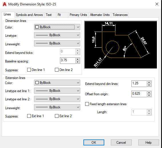
Fig. 6.9 Edit the dimension style is ISO-25
CREATION OF SOLID MODELS
The top design is to work in three dimensions. Three-dimensional models are of three types: wireframe, surface and solid.
For the convenience of working in 3D, you should choose a workspace 3D Modelling.
Modeling using the bodies is the easiest way to 3D Modelling. The AutoCAD allow you to create three-dimensional objects based on the basic spatial forms: parallelepipeds, cones, cylinders, spheres, wedges, and tor. Of these forms through their unification, subtraction and intersection are more complex spatial body. In addition, the body can build by sliding a flat object along zadannoy vector, or rotating it around the axis.
Solid object, or body, represents the image object that holds, among other things, information about its volumetric properties. Consequently, the body most fully of all types of three-dimensional models represent the modelled objects. In addition, despite the apparent complexity of the bodies, they are easier to build and edit than other models and network.
Modification of bodies is carried out by pairing their faces, and beveling. In AutoCAD there is also a command by which the body can be cut into two pieces or two-dimensional section.
As the network body look similar to wire models, until not one of them applied the operation of suppression of hidden lines, color, and toning. Unlike all other models, we can analyze the mass properties: volume, moment of inertia, center of mass, etc. Data about the body can be exported to applications such as systems of numerical control (CNC) and analysis by finite element method (FEM). The body can be converted into more simple types of models - the network and wireframe.
The density of the lines of curvature and used to visualize the curvilinear model is determined by the ISOLINES system variable. FACETRES system variable determines the degree of smoothing of stained objects with suppressed hidden lines.
Some concepts and definitions adopted in the three-dimensional solid modeling:
a face is a bounded portion of the surface. If the surface can be unlimited, as, for example, a planar (flat), conical, cylindrical, the face is always limited. Supported five types of faces: planar, cylindrical, conical, spherical, and toroidal.
edge — element, the boundary face. There are four types of edges: straight, elliptical(round), parabolic and hyperbolic. For example, a cube is limited by four rectilinear edges, and conical at the base of one elliptical or circular edge.
half space — part of a three-dimensional space lying on one side of the surface. Each surface is a boundary of two half-spaces, which is divided into three-dimensional space. 0O Half space — part of a three-dimensional space having a volume, and the surface — part of the three-dimensional space that has area but no volume;
the body is a part of space bounded by a closed surface and having a specific volume;
body (primitive) — simple (basic, basic) solid object that you can create and build from it a more complex solid model;
region — a part of the plane bounded by one or more planar faces, which are called boundaries. For example, a square with a circle inside has an outer boundary consisting of four straight edges, and internal — from one circular rib;
area (primitive) — a closed two-dimensional region, which is obtained by converting existing two-dimensional AutoCAD entities with a zero elevation (circles, shapes, two-dimensional polylines, polygons, ellipses, rings and strips), and is described as the body without the height;
composite region — a single region obtained by the logical operations of Union, subtract or intersection of several regions. It can have holes and in the same way as for solids, we can calculate the area and other characteristics. Integration of two-dimensional and three-dimensional design to create areas of solid and Vice versa. For example, automatically converting the cross section of the body in the area, you can calculate its area, and squeezing or rotating field, to create a complex body:
the object common name of the field or bodies, and the type of the object does not matter: it may be an area, body or composite model (group of objects connected together);
empty object— a composite body that has no volume, or a compound region, no area.
The simplest "building blocks" that comprise complex three-dimensional objects, called solid primitives.
Very convenient and easy is the creation of solid models by extrusion of plane figures. For example, drawing a circle, "squeeze" it to a certain height and get a cylinder. This way you can get the body shape.
Laboratory work.
Дата добавления: 2020-04-25; просмотров: 136; Мы поможем в написании вашей работы! |

Мы поможем в написании ваших работ!