Linear and parallel dimensions
Dimensioning in AutoCAD tape interface are implemented using bookmarks Annotations (Fig.6.1)

Fig. 6.1. Bookmarks Annotations.
The operations of setting dimensions, tolerances and extension lines (leader) are performed using the commands concentrated in the drop-down menu Dimensions (Fig. 6.2)
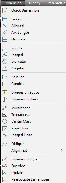
Fig. 6.2. Drop-down menu item Dimensions

Fig. 6.3. The drop-down menu
DIMLINEAR – is designed for installation in linear dimensions.
 It corresponds to Linear Dimension panel Dimensions and item Linear falling menu Dimensions.
There are two options for performing work. The first option. For placing horizontal size is specified using temporary or permanent object snaps, point to the upper-left corner of the rectangle (Fig. 6.3) and in response to the request of AutoCAD: Specify second extension line origin: use the object snap to specify the upper right corner. AutoCAD asks where to place the dimension line.
The information on the object, AutoCAD determines which dimension type (horizontal, vertical) you want to build. If you agree with this, it remains with the mouse to specify the endpoint of the level at which to set up the size and press the left mouse button. Built size is a single object (entity size). If you select it with the mouse it is highlighted all the way through. If necessary, you can expand the size into simpler components using the command EXPLODE.
Similarly, you install the vertical size of the rectangle.
You can decide to change the type of linear dimension if, instead of the position of the dimension line, select one of the options:
-Horizontal — add a horizontal dimension;
-Vertical — add vertical dimension:
-Rotated — add a rotated (inclined) size. AutoCAD will prompt: the Angle of the dimension line: (Specify angle of dimension line:), at that angle you can set a number on the keyboard or again to specify two points at the ends of the measured object, and the system will calculate the required angle of rotation;
Angle — set angle of the dimension text relative to dimension lines;
-Text — enter another dimension text different from the text proposed by default.
-Mtext — to introduce more complex dimension text using the capabilities of mtext.
In addition to specifying the two points between which we need to set size, there is another option–to use the option<select object> (<select object>), which comes into effect if the first extension line press the Enter key. The following query:
|
|
|
Select object to dimension: (Select object to dimension ).
You need to specify the line or line segment of the polyline. AutoCAD object calculates the end point and then issuing a regular query about the position of the dimension line and related options.
 Command DIMALIGNED correspond Aligned Dimension panel Dimensions and item Parallel (Aligned) falling menu Dimensions. This command allows you to designate a linear dimension parallel to the selected segment or two specified points.
 Command DIMORDINATE allows you to build a leader by setting the value of the abscissa or ordinate of the specified point. This command button correspond to an Ordinate Dimension panel Dimensions and paragraph Ordinate falling menu Dimensions.
You need to specify the point at which the end extension line. The system itself is trying, using the slope of the extension line to determine which of the two coordinates (the abscissa or the ordinate) should be put on the field of the drawing.
Дата добавления: 2020-04-25; просмотров: 153; Мы поможем в написании вашей работы! |

Мы поможем в написании ваших работ!