Tractor Power Take-Off Torque Measurement and Data Acquisition System
Matching implements correctly to effectively utilize tractor power has been a
continuing research pursuit with the advancements in machinery technology. Annual tractor competitions in early 20th century Winnipeg were held to test: fuel and water economy, maximum engine and belt power output, draft test, and design and construction of the tractor (Ellis, 1913). The tractor transmits power to the implement through several systems independently: draft power is transferred via the drawbar or 3-point hitch, fluid power is available by way of one or more hydraulic remote blocks, rotational power is transmitted from the engine through a gear train to the power take-off (PTO) shaft, and electrical power may be provided through multiple electrical outlets inside and outside the tractor cab. The most efficient transmission (90 %) of net engine power (Fig. 1, ASAE D497.7, 2015) for an agricultural tractor to a towed implement whether stationary or mobile is via the PTO shaft (Fig. 5.1).
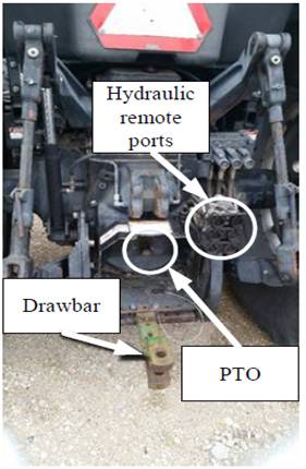
Figure 5.1. Typical location at the rear of an agricultural tractor for delivery of power to implements.
Significant changes have been made to the tractor’s PTO power delivery since being commercially available for the first time in 1918 on International Harvester Company’s (IHC) model 15-30 (Goering and Cedarquist, 2004). The 21-spline 1000 rev∙min-1 shaft standard was created in 1958 followed by a 20-spline “large” 1000rev∙min-1 shaft. A new 1000 rev∙min-1 shaft with 22-splines was created and included in the latest ISO standard (ISO 500-3:2014). Currently, the standard includes location and dimensions of the PTO shaft, coupler (ISO 500-3:2014), master shield, clearance zone and general safety requirements (ISO 500-1:2014). The 500-1 standard recommends the maximum PTO power that can be transmitted at rated engine speed for each PTO type. Most of the power and speed requirements of implements are calculated by the implement manufacturers and are dependent on gear boxes and implement load, while thetractor manufacturers anticipate and calculate which tractors will be able to power theseimplement loads and install the appropriately sized PTO transmission.
Tractor PTO power measurement research using data acquisition systems (DAQs)have been performed utilizing fuel consumption data (Sumner, et al., 1986) to determinetotal implement power. Load differences between implement operations allowed theauthors to estimate separation of power into draft requirements, PTO powerrequirements, travel requirements, and a crop load as operated for 3 minutes or one baledepending on the mode. A study by Vigneault et al. (1989) used a torque meter secured toa cart to measure PTO power. The cart was connected to the tractor drawbar and the cartcould attach to an implement via the implement drawbar or the implement 3-point hitch.Limitations of such a cart were the increase in overall machinery length and a possiblesafety hazard if sufficiently acute steering caused the cart or implement to uncontrollablyskid into the rear wheels of the tractor causing an overturn. The cart did have benefitssuch as the ability to connect multiple PTO types using different shafts. Bending or shearstresses on the sensor were avoided by having universal joints on both shafts connected tothe sensor. Modifying the implement PTO shaft to include a built-in slip ring torquetransducer was previously done for energy mapping (Kheiralla and Yahya, 2001). Themodified shaft replaced the current shaft on the implement. This shaft was welded to auniversal joint with a female coupler limiting the sensor to one size of PTO shaft withoutaltering the universal joint and coupler. The rotary power table presented in the ASABEstandards (Table 2, ASAE D497.7, 2015) was based on the research of Rotz and Muhtar(1992). Many of the parameters in the table are currently the same values based on theoriginal research over 20 years ago. Not all of the rotary implements have made vast improvements over the last two decades. However, with the increased implementation of embedded systems in agriculture, controller area network (CANBUS) and ISOBUS, variable rate application, and increasing machinery size, some parameters values may be less representative of current equipment and have become outdated. A review of the
|
|
|
rotary power requirement data proves to become beneficial as implements emerge use the embedded systems to communicate implement power requirements with the tractor.
This paper presents a different approach to measure PTO power delivered to a towed implement. The approach used to complete this research used a commercially available slip ring torque transducer that involved no modifications to the tractor or implement PTO shaft. One of the requirements of the PTO torque sensor was the ability to fit on at least one standard PTO shaft size, allowing the sensor to be mounted onto tractors with the same size PTO shaft.
|
|
|
Materials and methods
A PTO data acquisition system capable of measuring and recording torque and rotational speed was developed. The system was based on instrumented slip ring transducers commercially available, to be used as the device under test (DUT). The selected transducers for torque measurement acted as an extension of the PTO shaft at the rear of the tractor. Two sensors were evaluated and one was deemed appropriate based on preliminary evaluation and testing.
PTO Torque Sensors
Slip-ring torque transducers with flanged ends were easily obtain commercially.
However, manufacturing couplers and shafts to mount these sensors in a compact
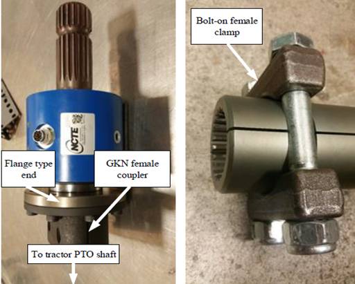
package proved to be difficult. Ready-to-use PTO torque transducers were available from two vendors (Datum Electronics, United Kingdom and NTCE AG, Germany). These sensors have PTO couplers and shafts mated directly to the measurement shaft instead of having flanged ends. The connections used for this research were the 45 mm (1 ¾ in.) 1000 rev∙min-1 20-spline configuration shaft and coupler.
1.1 Datum Electronics Series 420 PTO Shaft Torque and Power Monitoring System
1.1.1 Device description
The Datum PTO system (Series 420, Datum Electronics, Ltd., East Cowes, Isle of Wight, United Kingdom) was a slip-ring based torque transducer with optional shafts and coupler arrangements to meet the needs of PTO torque measurement. This sensor was not used due to safety concerns.
1.2 NCTE 7000 Torque Sensor for PTO-shafts
1.2.1 Device description
The NCTE torque sensor (7000 series, NCTE AG, Unterhaching, Germany) was a slip-ring based torque transducer with available flanged ends or a male and a clamp-type female PTO shafts (Fig. 5.3a, 5.3b).
Дата добавления: 2018-04-15; просмотров: 221; Мы поможем в написании вашей работы! |

Мы поможем в написании ваших работ!