Figure 3.2 (a) DUT in a 90-90 tubing configuration, (b) DUT in 0-0 and 45-45 tubing configurations.
Tractor Drawbar Force Measurement and Validation.
The tractor drawbar is the most widely used method of towing an implement. An
accurate, robust method for measuring the draft load developed by a towed implement has been a critical industry need for some time. Tractor tests were conducted as far back as 1908 in the Winnipeg Tractor Trials (Ellis, 1913). Some approaches for draft force measurement include: attaching a load cell to the drawbar; or a hydraulic cylinder acting as a load cell, which has been used for official drawbar draft measurements at the Nebraska Tractor Test Laboratory (NTTL) as recently as 2011; installing an instrumented drawbar pin; or instrumenting the drawbar itself. An objective of this sensor was to minimize alterations to the tractor components while determining the amount of force generated by a towed implement. Fastening a load cell to the end of the drawbar was discounted as such a system created a cantilevered load that affected the tractive efforts of the tractor. In addition the load cell needed to be rigidly mounted to prevent excessive lateral movement during turning or stopping, which had the potential to cause damage to the load cell, the tractor as well as provide and unacceptable risk of personal injury to the operator. A design complication of using a load cell that would not pivot, was that the load cell proved ineffective in measuring lateral loads as seen in contour or headland operations. Another method of integrating the load cell into the drawbar was to permanently alter the drawbar which required a replacement drawbar to be installed after data collection was complete. Drawbar pin instrumentation was a possibility, but had the potential to create an unacceptable level of noise in the data due to the often large tolerances between the drawbar, pin, and implement tongue. Another approach of applying strain gages to the pin where the drawbar transfers load to the rear axle housing was suitable to reduce the noise since tolerance of this connection are well controlled. A disadvantage of this method was that since the pin rotates freely, a directional strain error was generated, minor design steps were required to ensure that the pin could not rotateduring data collection. A pin of this design requires additional development time and testing to ensure proper strain and alignment when compared to the chosen alternative.
Instrumenting the drawbar with strain gages was the most effective method for measuring draft for the intended study. One major difficulty with instrumenting the drawbar was the calibration of the strain gages on multiple agricultural machinery setups. Each drawbar needed to be calibrated, which required either an appropriate calibration test bench that could be transported to all application sites or removal of the drawbar from the test tractor for a period to allow for lab instrumentation and calibration. Previous studies have tried to determine the amount of power required to pull an implement via the drawbar including: Wendte and Rozeboom (1981), Grevis-James and Bloome (1982) and Graham et al. (1990). These studies developed data acquisition systems (DAQs) that were capable of measuring the amount of force applied to the drawbar by an implement and ground speed of the machinery with wheel slip. Graham used a hydraulic load cellattached to the end of the drawbar, while most others used a modified drawbar instrumented with strain gages. All of these studies modified a component of the tractor to measure the tractive efficiency with their main purpose being to properly size tractors for tillage and planting operations. The Organisation for Economic Co-operation and Development (OECD) requires that draft force measurements be within 1 % (section3.4.2, OECD Code 2, 2016).
This paper presents a different approach for determining the draft force of a towed implement. This approach minimized alterations to tractor components, which allowed the system to be mounted onto multiple tractors of similar size with few modifications.
Materials and methods
An instrumentation system to measure and record draft force on the drawbar was
developed. This system consisted of a drawbar instrumented with strain gages and data acquisition hardware. The drawbar draft force measurement system was connected to a load cell integrated into the hitch of a dynamometer car for evaluating the measurement accuracy.
Measuring Devices
For an initial prototype design, an instrumented drawbar was deemed an appropriate device under test (DUT). The ideal location to minimize vertical loading in the strain gage measurement was as close to the front drawbar support as possible (see Fig. 4.1a). The wiring and the strain gages required protection from debris. Material was milled from the surface of the DUT to increase the sensitivity and provide a smooth surface to mount the strain gages (Fig. 4.1a). Two 90 degree strain rosettes (Micro-Measurements EA-XX-125TQ-350, Vishay Precision Group, Inc., Wendell, N.C.) were mounted on either side of the DUT (Fig. 4.1b) to measure the axial load. A cross-drilledhole provided a raceway between the rosettes for the sensor wires to be routed safely (Fig. 4.1b). The strain gages on the rosettes were wired in a full-bridge temperature compensated configuration (Fig. 4.1c). The DUT was interfaced using a National Instruments (NI) compact DAQ (NI 9174, National Instruments, Austin, Texas) with a universal analog module (NI 9219, National Instruments, Austin, Texas) which was capable of providing the excitation voltage of +2.5 V and amplification of the strain gage signal output (Fig. 4.1d).
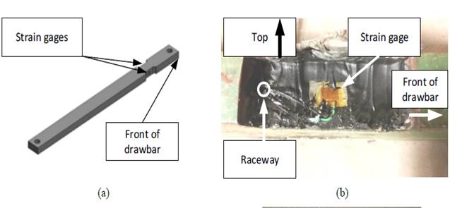
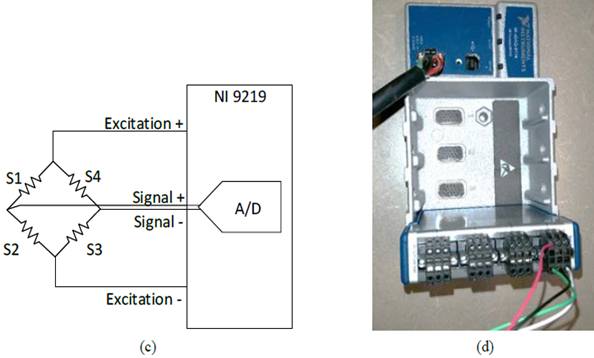
Figure 4.1 (a) Drawbar (DUT) illustrating sensor location, (b) focused side view where strain gage rosette was placed on drawbar, (c) Circuit diagram illustrating the bridge configuration as attached to DAQ module, (d) NI cDAQ with NI 9219 module wired as a full-bridge design.
Дата добавления: 2018-04-15; просмотров: 221; Мы поможем в написании вашей работы! |

Мы поможем в написании ваших работ!