The Values Taken by Adjustable Resistor Slider
At the leftmost position it reads as 0, at the rightmost position — as 100.
The Values Taken by Black Button
On pressing this button, its value toggles from false to true and vice versa.
The Values Taken by Coloured Buttons
On pressing any of these buttons, its value toggles from 0 to 100 and vice versa. All the buttons have a usual group of contacts: a couple of fixed contacts and a movable contact between them. At the movable contact, a rod is fastened that protrudes out of the case of the circuit board.
Calibration of Temperature Sensor
To calibrate a temperaturesensor, we are going to measure the temperature of water being continuously heated up, and we put the readings, taken from a thermometer and from a sensor panel, into Table 3. Make a graphical plot based on the data of the table (Fig. 16).
Table 3. Relation between the Values Taken from the Attachable Temperature Sensor and the Household Thermometer
| Термометр, градусы | 0 | 5 | 10 | 15 | 20 | 25 | 30 | 35 | 40 | 45 | 50 |
| Датчик температуры, ед. | 0,6 | 2,2 | 4,3 | 6,7 | 9 | 11,1 | 13,7 | 15,8 | 17,9 | 20,2 | 22,5 |
The trend line (approximation of the function) shows that the relation between the values taken from the attachable temperature sensor and from the household thermometer is linear and can be expressed by Formula 2:
y = 0,4497x - 0,4165 (2)

Fig. 16. The relation between the data obtained
from the attachable temperature sensor and from the household thermometer.
For a whole host of projects, not only direct but also an inverse dependency of the said meterages can be required. To that effect, just derive the inverse relationship, expressing х by у:
х = 2,2237у + 0,9261 (3)
 Sensors calibration Calibration of the sensor is a specific area of educational research performed using the ScratchDuino.Lab. The measurements can be made by different meters and following different methods. The measurement errors also can differ. Within the framework of ScratchDuino community (see about it below), you can offer your own meterage and formulas. You can also share with other members of this community the experience concerning the calibration of the sensors, the ones shipped with the kit or additional.
Basic Concepts of Scratch
Scratch is a computer model of the real world. Its environment with the items of graphical user interface (GUI) is shown in Fig. 17.
|
|
|


Fig. 17. The Scratch environment:
1 — Info Panel; 2 — the Block Palette (groups of commands) ;
3 — the Script Area; 4 —Control group; 5 — the Actor (sprite);
6 — background of current Stage; 7 — the Sprites Panel ; 8 — the Stage area.
The world of Scratch consists of many objects (the word “object” stems from Latin objectum, which means a thing) populating a common space. The objects are anything that exists in the nature: people, animals, wind, snow, tree,
sun, letters, ice-cream, candies and all.
The objects can also be Actors to implement the algorithms.
An algorithm is an exact, step-by-step instruction determining the behaviour of the Actor(s) that brings the data (taken, for example, from the ScratchDuino.
Lab sensors) to a required result. Development of an algorithm is a creative process. An algorithm can be represented as a script.
Scripts in Scratch and in ScratchDuino are made of ready blocks-commands, resembling the bricks of Lego. This syntax is quite intuitive. To make a script, you have to join several blocks (just snap them together in the Script Area). The blocks and the order they follow each other are important, because they define what an Actor is going to do.
Actors in Scratch are depicted by sprites (Sprite is a supernatural creature, an elf), while the space where the events are happening is a Stage. The Stage can be an Actor too. The stories in Scratch are described using the algorithms. There are only two kinds of Actors in Scratch: the Stage and the sprites.
Sprites, either created by the users, or downloaded or found in a sprite library, are the Actors that operate within the project. Many projects include, as a minimum, one sprite that can move around the project screen, unlike the stage.
Except for running the commands, a sprite can change its costume. The appearance of a sprite can be changed directly or with the commands in the scripts editing area. To change a costume, you need to go to the Costumes tab, found next to the Scripts and Sounds tabs. The Costumes tab contains the whole list of costumes, and the costumes can be modified or imported from a sprite library or from your PC. You can create and add a new costume as well.
|
|
|
The Stage includes a set of images found under the Backgrounds tab (Fig. 18), which are background for the sprites’ actions. On launching the program, a background image is ready: it is a white rectangle, 480-pixel wide and 360-pixel high. A “pixel” is a dot, a minimal component of rasterized computer graphics.

Fig. 18. The Backgrounds Tab.
The command set for the sprites consists of 125 commands, while for the stage there are 85 of them. This set allows for the implementation of a vast variety of algorithms. All the commands are found at the top-left pane of the program window (the Block Palette), distributed into eight groups. The groups are highlighted with different colours: Motion, Looks, Sound, Pen, Control, Sensing, Operators, and Variables.
Projects in ScratchDuino consist of several scripts for the sprites, performed simultaneously (in parallel) using one or more costumes (Fig. 19).
Fig. 19. The structure of a project in Scratch.
Highlighted is the mandatory part.
The rest depends on the author’s design .
To describe the projects in Scratch, the following pattern is used:
¾ theme;
¾ requirements to meet;
¾ description of the project progressing and/or explanations for the script;
¾ the picture of the script.
Basic Algorithms of Scratch
The algorithmscan be divided into three kinds as of their structure: linear, branching, and loops.
Linear algorithm is such one, for which all the commands are done one after another and only once. Its script is a sequence of blocks, following from top to bottom in the order of their performing.
Theme: “The Crab Draws the Stairs”.
Requirements:
¾ the Actor is the Crab;
¾ the drawing is made like in an animated cartoon;
¾ an easy option to change the number of stair-steps and their size is provided;
¾ the script runs if the value of Slider variable is greater than 50.
|
|
|
Implementation of the project “The Crab Draws the Stairs”
using a linear algorithm
We have to teach our Crab to draw the stairs. The Crab lives in a rectangular field of a size 480×360 pixels and knows how to locate a place in the field by its coordinates [2] . The Crab can make a prescribed number of moves; wait; and point in the directions left and right by 0, 90, and 180 degrees. The Crab has a pen that leaves a line when put down. A script for the Crab is shown in Fig. 20. As per this script, the Crab draws 3 steps (Fig. 21). The script starts running on pressing the “up arrow” key.
If you use a purely linear algorithm:
¾ the process of “building” the stairs is not visible, but the picture appears instantly;
¾ changing the number of stair-steps needs to make the script longer and to edit numeric values in each block, so this method cannot be called easy;
¾ the requirement concerning the Slider cannot be met.


Fig. 20. Linear algorithm to draw the stairs.

Fig. 21. The result of linear script for Sprite 1 in a Crab costume
at a Stage with white background (courtesy of crab1-a collection).
Conclusion 1.When only the linear algorithm is used, you cannot meet all the requirements.
Loop algorithms. A loop is a series of commands to be repeated until a specified condition becomes true. Thanks to the operators controlling the loop, the script can be done much shorter. Scratch provides the blocks for four kinds of loops: unconditioned (endless); with a counter; with a pre-condition; and with a post-condition (Fig. 22).

Fig. 22. Loops in Scratch.
Implementation of the project “The Crab Draws the Stairs ”
using a linear algorithm and a loop
It is easy to notice that in Fig. 20, a set of commands is repeated: make 60 moves, point in the direction 0° (upwards), make 40 moves, point in direction 90°. That means we can use a loop.

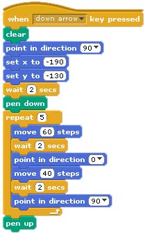
Fig. 23. A loop .
Notice that the script in Fig. 23 is shorter than in Fig. 20, and the Crab has drawn 5 stair-steps (Fig. 24). Now it will be enough to change the value in the repeat box, and you will have as many stair-steps as you like. If we change the number of the moves (the height of a stair-step) from 40 to 20 in just one block, all the stair-steps will change.
|
|
|
When we use a loop:
¾ the process of “building” the stairs is not visible anyway;
¾ we have managed to meet the requirement about easily changing the number and the size of the stair-steps;
¾ the requirement concerning the Slider cannot be met yet.
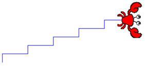
Fig. 24. The result of script with a loop for Sprite 1 in a Crab costume
at a Stage with white background (courtesy of crab1-a collection).
Conclusion 2.When only the linear algorithm and a loop is used, you cannot meet all the requirements of the project “The Crab Draws the Stairs”.
Branching algorithms. An algorithm is called branching if it has several options to choose for a further action. The choice can be simple (in case of two alternative options) or complicated (when there are more than two options) (Fig. 25).

Fig. 25. A complicated choice .
The moment of a choice is called the branching point. Branching is one of the three basic structures of algorithms (along with the linear flow of commands and the loop). All the programming languages have special operators (or commands) — conditional operators, to implement an action depending on a stated condition. Scratch has three conditional operators in its Control group: complete branching (IF-THEN-ELSE), incomplete branching (IF-THEN), and pause (WAIT UNTIL) (Fig. 26).
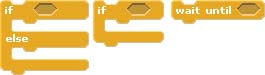
Fig. 26. Conditional operators in Scratch .
Implementation of the project “The Crab Draws the Stairs ”
using a linear algorithm, a loop, and a branching
As shown in Fig. 27, the ready script (Fig. 23) was added by:
1) two blocks of pauses  , enabling you to see (like in an animated cartoon [3] ) the process of drawing the stairs;
2) a block of incomplete branching  , that checks the value of the Slider variable from the connected ScratchDuino.Lab. In accordance with the specified condition, the script runs if the Slider rests at the right-hand side of its “lane”, that is, the value of the Slider variable is greater than 50.


Fig. 27. An algorithm with branching.
Conclusion: The project can be implemented in full only in case when all three kinds of algorithms (linear, loop, and branching) are used.
Дата добавления: 2019-01-14; просмотров: 293; Мы поможем в написании вашей работы! |

Мы поможем в написании ваших работ!