Determinationofcombustionparameters
The combustion equation looks like following:
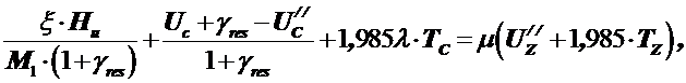
where  - pressure build-up.
For pre-chamber and vortex-chambered diesel engines is taken closer to the lower limit, and for engines with direct injection closer to the upper limit.
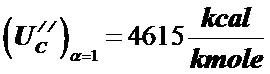
According to the diagramU = f (t)values of the internal energy of gases in the temperature range300…9000С (pic. 2.1.) we find graphically for the compression temperaturetС = ТС – 273 = 1035 – 273 = 7260Сinternal energy of 1 kmole of airUC = 4113  and internal energy of 1 kmole of combustion products for diesel fuel atα = 1,0
 ,
,
The internal energy of 1 kmole of combustion products at a compression temperature tC includes the internal energy of the combustion products atα = 1.0 and internal energy of excess air. that is,
 ,
,
where 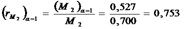 – relative amount of combustion products, withα = 1,0 in 1 kmole of combustion products at
α = 1,35;
 – relative amount of excess air in 1 kmole of combustion products.
Then the internal energy of 1 mole of combustion products at the compression temperaturetС
 .
.
We set the value, let  = 1,8.
Then the sum of all the terms on the left side of the combustion equation 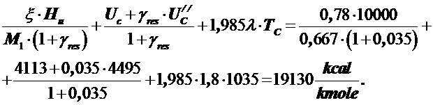
From here 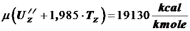 .
.
Because  , so
, so  .
.
Value of  s a function of the combustion temperature and heat capacity, so the last equation can be solved by the selection method, using Table 2.1 or Fig. 2.2 in the temperature rangetZ = 1800…21000С.
Let take the valueoftZ =20000Сand find 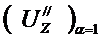 and
and  for this temperature.
Giventhat 
 , then
 .
.
The values  и
и  ofair are taken from the table 2.1 for the respective temperature values.
The result is less than necessary, so we set the temperaturetZ = 21000С. When:
 .
.
In this case:  .
.
Since the right-hand side of the combustion equation is  and it is less than
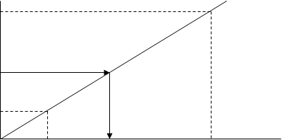
  , it is obvious that the desired temperature is between 20000and 21000С. To do this, we plot a graph (fig. 3.1) and determine the desired temperature graphically.
It can be seen from the graph thattZ = 20340С.
Then the temperature at end of the combustion
 .
.
Maximumcombustionpressure:
 .
.

 18000
18000
17500
17000
1900 2000 tZ0 С.
Рис. 3.1. Dependency from the temperaturetZ0С.
|
|
|
3.6.
Calculationofexpansionparameters
1) Preliminaryexpansion
 .
.
2) Subsequentexpansion
 .
.
3) Expansionendpressure
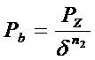 ;
;  .
.
4) End-of-ExpansionTemperature
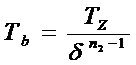 ;
;  .
.
5) Mean calculated indicated pressure of the cycle
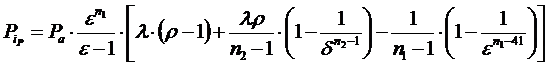 .
.
6) The actual average indicated pressure, taking into account the curvature factor of the indicator diagram.
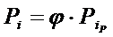 ;
;  .
.
KeyPerformanceIndicators
1) The proportion of indicated pressure used for friction and drive of auxiliary units
 .
.
For pre-chamber and vortex chamber diesels
 .
.
2) Mean effective cycle pressure
 ;
;  .
.
3) Mechanicalefficiency
 ;
;  .
.
4) Specificindicatedfuelconsumption
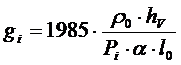 ,
,
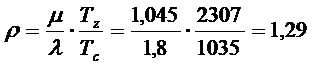
гдеρ0 –density of the charge at the inlet, кg / м3,
 ;
;  ;
;
l0 – theoretically required amount of air (in kg) for combustion of 1 kg of fuel.
5) Indicatedefficiency  ;
;  .
.
6) Specificeffectivefuelconsumption:  ;
; 
 .
.
7) Effectiveefficiency  ;
;  .
.
Basicdimensionsofthe engine
1) Calculatedvolume of one cylinder
 .
.
2) Diameter of the inner surface of the cylinder:
 .
.
3) Pistonstroke
 .
.
Finally, for the convenience we round up values to integers.
Speed  should not differ from the chosen one by more than 5...10 %, otherwise, it is necessary to recalculate the effective indicators.
4) Enginedisplacement  .
.
5) Effectivepower  .
.
6) Indicatedpower  .
.
7) Volumetricpower  .
.
8) Effective and indicated torque
 ;
;
 .
.
Дата добавления: 2018-02-28; просмотров: 267; Мы поможем в написании вашей работы! |

Мы поможем в написании ваших работ!