Unit 4. Practice in working with GB and US Patent Specifications
1. Read and translate the following Patent Specifications, attracting attention to the structures of the text.
2. Mark and write down the information of the inventor, assignee or patent holder and validity of the patent.
3. Find out all communicative blocks which can help you to understand the spirit of the invention.
[12] UNITED STATES PATENT [10] Patent No .: US 7,746,381 B 1
Ye at al. [45] Date of Patent: Jun. 29, 2010
[54] MULTI-DISPLAY DIGITAL PHOTO FRAME
[75] Inventors: Jia-Yong Ye, Shenzhen (CN); Gao-Hui Tang, Shenzhen (CN)
[73] Assignees: Hong Fu Jin Precision Industry (Shenzhen) Co., Ltd., Shenzhen, Guangdong Province (CN); Hon Hai Precision Industry Co., Ltd., Tu-Cheng, Taipei Hsien (TW)
[*] Notice: Subject to any disclaimer, the term of this patent is extended or adjusted under 35 U.S.C. 154(b) by 0 days.
[21] Appl. No.: 12/432,710
[22] Filed: Apr. 29, 2009
[30] Foreign Application Priority Data
Jan. 5, 2009 (CN)…………………….2009 2 0300041
[51] Int. Cl.
H04N 5/225 (2006.01)
[52] U.S. Cl…………………………………………………………348/207.99
[58] Field of Classification Search……………………………….348/207.99; 345/55
See application file for complete search history.
[56] References Cited
U.S. PATENT DOCUMENTS
6,266,069 B1 * 7/2001 Thagard et al. 345/638
7,203,380 B2 * 4/2007 Chiu et al. 382/284
2004/0257348 A1 * 12/2004 Ou 345/204
2007/0291153 A1 * 12/2007 Araki et al. 348/333.05
2009/0256780 A1 * 10/2009 Small et al. 345/55
* cited by examiner
Primary Examiner – James M. Hannett
Attorney, Agent, or Firm – Zhigang Ma
[57] ABSTRACT
A multi-display digital photo frame is provided. The multi-display digital photo frame includes a front cover, a rear cover, and a body. The front cover includes at least two apertures, the body includes at least two holding components for placing LCDs, the bottom of each holding component mounted a LCD further for mounting a processor, wherein the processor is connected to the corresponding LCD through a bus.
Claims, 2 Drawing Sheets


BACKGROUND
1. Technical Field
|
|
|
The present disclosure relates to a multi-display digital photo frame.
2. Description of Related Art
Digital photo frames are intended to conveniently display images without the need to print the images out. Displaying images is an essential function of digital photo frames, therefore, various manners for displaying images will be an important element for attracting customers. However, many digital photo frames have only a single LCD, accordingly, forms of displaying images with a single LCD are restricted. Therefore, what is needed is a digital photo frame with multiple displays, which can overcome the aforementioned shortcomings.
BRIEF DESCRIPTION OF THE DRAWINGS
The components of the drawings are not necessarily drawn to scale, the emphasis instead being placed upon clearly illustrating the principles of a multi-display digital photo frame. Moreover, in the drawings, like reference numerals designate corresponding parts throughout several views.
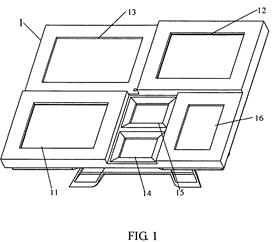
FIG. 1 is a perspective view of a multi-display digital photo frame in accordance with an exemplary embodiment.
FIG. 2 is an exploded perspective view of a multi-display digital photo frame according to an exemplary embodiment.
DETAILED DESCRIPTION
Referring FIGS. 1-2, a multi-display digital photo frame 1 in accordance with an exemplary embodiment is provided. The multi-display digital photo frame 1 includes a front cover 10, a body 20, and a rear cover 40 having a bracket for supporting the multi-display photo frame 1. The front cover 10, the body 20, and the cover 40 are connected together through bolts (not shown).
The front cover 10 defines several apertures 11-16 thereof. The shape of the apertures 11-16 can be rectangular, circular, and so on. For example, in the embodiment as shown in FIG. 1, the apertures 11-16 are rectangular.
The body 20 includes several holding components 21-26. The number of the holding components 21-26 is equal to the number of the apertures 11-16, and the holding components 21-26 are substantially the same shape as the apertures 11-16, by this arrangement, the front cover 10 and the body 20 can be fastened together. In addition, at least two of the holding components 11-16 are configured for mounting LCDs (Liquid Crystal Display), and a processor is provided for each LCD. For illustrative purpose, hereinafter, two holding components 21 and 22 configured for mounting LCDs are taken as an example. The holding component 21 mounts a LCD 27, and the bottom of the holding component 21 further mounts a first processor 31, and the LCD 27 is connected to the first processor 31 through a bus 28. The holding component 22 mounts a LCD 29, and the bottom of the holding component 22 further mounts a second processor 32, and the LCD 29 is connected to the second processor 32 through another bus 30. One of the processors (e.g., the first processor 31) is regarded as a master processor, and the other of the processors (e.g., the second processor 32) is regarded as a slave processor. The master processor 31 is connected to a power source, an input unit, an interface, and so on, and is further connected to the slave processor 32 through a bus, e.g., a USB bus.
|
|
|
The other holding components 23-26 are configured for holding printed photos and having a transparent material to cover and protect the photos.
Although the present embodiments have been specifically described as examples, the disclosure is not to be construed as being limited thereto. Various changes or modifications may be made to the embodiment without departing from the scope and spirit of the invention.
CLAIM
1. A multi-display digital photo frame comprising:
· a front cover comprising at least two apertures;
· a rear cover; and
· a body comprising at least two holding components, wherein each of the holding components is configured for mounting an LCD exposed via one of the at least two apertures, the front cover and the body being mounted to the rear cover, and each holding component is further for mounting a processor, and the processor is connected to the corresponding LCD through a bus.
2. The multi-display digital photo frame as described in claim 1, wherein the number of the holding components is equal to the number of the apertures, and the holding components are substantially the same the shape as the corresponding apertures.
|
|
|
3. The multi-display digital photo frame as described in claim 1, wherein one of the processors is connected to an input unit, an interface, and a power source, and is further connected to other processors through the bus.
4. The multi-display digital photo frame as described in claim 1, further comprising other holding components for holding printed photos thereon.
4. Retell the contents of these Patent Specifications using the given below questions as a plan.
1) What is the title of the invention?
2) What county does the patent belong to?
3) What are the key words of the Patent Specifications?
4) What is the first country of patenting?
5) Who is the inventor?
6) Is there any assignee?
7) Is there any information about prior publication or foreign priority?
8) What is the date of patenting?
9) When was the Patent Specification published?
10) What can you get from the abstract of the Patent Specification?
11) How many claims and drawing sheets are there in the Patent Specification?
12) What field of art does the invention relate to?
13) Is there any background of the invention?
14) What is the technical problem to be solved by the invention?
15) What is the aim of invention?
16) What is the main idea of the invention?
17) What are the main invention's peculiarities?
18) What can you say about this invention? Is it useful?
Unit 5. Revision
Дата добавления: 2019-09-08; просмотров: 340; Мы поможем в написании вашей работы! |

Мы поможем в написании ваших работ!