Matrix (low pressure) acidizing
Nbsp; Completion refers to the process of making a well ready for production (or injection). This principally involves preparing the bottom of the hole to the required specifications, running in the production tubing and its associated jewellery and perforating and stimulating as required. Sometimes, the process of running in and cementing the casing is also included.
Completion basics
The economic success of a well depends in large part on making the optimum connection between the wellbore and the reservoir system. That optimum connection must perform three functions:
1. let oil into the well, where it can then flow or be pumped to the surface;
2. keep over – or underlying water out of the well;
3. keep the formation out of the well.
Although “completion” has never been universally defined, this concept is its basis. Neither is there universal agreement on the point at which completion begins. Probably the most widely held view is that completion begins when the bit first makes contact with a productive formation. Completion design is a function of numerous reservoir characteristics, such as permeability, porosity, saturation, pressure, stability and compartmentalization. According to King G. E. (Introduction to the Basics of Well Completions, Simulations and Workovers, 1996), the key to a good initial completion is to collect and assess as much data as possible that are relative to these interrelated characteristics at the earliest possible time.
Porosity and permeability are the reservoir storage and pathway of flowing fluids. Porosity is the void space between the grains where fluids can be stored. Permeability is a measurement of the ability of fluids to flow through the formation. The higher the permeability, the more easily a fluid can flow through rock matrix. Most productive formations are between 0.001 and 1.000md. Porosity does not always relate directly to permeability. Materials, such as shales and some chalks, for example, may have very high porosities but low permeability because they lack effective connection of the pores. When evaluating a reservoir economic potential, a porosity or permeability cutoff level often is used to establish minimum pay requirements. This level can be determined from porosity log and flow tests.
Saturation in almost every porous formation, there is at least a small amount of water saturation. The remaining fraction of the pore space that contains oil or gas is the hydrocarbon saturation. In general, the most productive parts of a reservoir usually are those with higher hydrocarbon-saturation values. Water saturation also may be a key determinant of pay because extremely high water saturation could indicate hydrocarbon depletion or movement of an aquifer into the pay. Closely related to porosity and saturation are recoverable hydrocarbon volumes. Not all oil in place can be recovered. The amount of oil that will flow from a rock depends on the size of the pore spaces, the oil saturation and type and the amount of energy that is available to push the oil toward the wellbore.
|
|
|
Reservoir Pressure the pressure that the reservoir fluids exert on the well at the pay zone, dictates how much fluid ultimately is recovered. Reservoir pressure varies throughout the productive life of a reservoir. Initial reservoir pressure is the pressure at the time of discovery, but there are other forces involved. These forces or drives include solution-gas drive, gas cap, and water drive. While many pressure regimes are present and important during the life of a well, pressure differential toward the wellbore is essential for fluid flow during completion and production.
Reservoir Stability can affect the initial completion as well as repairs or recompletions throughout a reservoir life. Many geologically young formations lack sufficient strength for formation coherency during all phases of production. These younger rocks often require stabilizing or sand-control, types of completions to support the formation while allowing it to flow fluids.
Compartmentalization is the division of a reservoir into compartments that are partially or fully pressure isolated by faults, permeability or porosity pinchouts, folding, shale streaks, barriers or other factors. The more that is known about these reservoir characteristics and their interactions with one another, the better the chances of selecting the optimal pay, deciding where to place the wellbore, and establishing the critical link between the wellbore and the formation.
Types of completions
There are three primary inflow completion types: natural, stimulated and sand control.
|
|
|
1. Natural completions are those in which little or no stimulation is required for production. Sandstone and carbonate systems with good permeability and mechanical stability are prime candidates for natural completions.
2. Stimulated completions generally are applied to improve the natural drainage patterns of hard, low-permeability formations or to remove barriers within the formation that prevent easy passage of fluids into the wellbore. Acidizing and hydraulic fracturing are examples of stimulated completions.
3. Sand-control completions are performed in young, unconsolidated or less mechanically competent sandstones to support the formation while allowing it to flow fluids.
| completion: | |
| cased hole well | заканчивание скважины с обсаженным забоем |
| bare foot | законченная бурением скважина с необсаженным стволом у забоя |
| bare foot well | заканчивание скважины без спуска обсадной колонны в продуктивную зону; заканчивание скважины с необсаженным забоем |
| casingless | заканчивание морской скважины с опорой на дно |
| conventional | заканчивание скважины, при котором в нее опускается колонна обсадных труб диаметром не менее 4.5 дюйма |
| drainhole well | заканчивание разветвленной скважины, многозабойное заканчивание скважины |
| dual | 1) закачивание скважины в двух горизонтах; 2) двухпластовая скважина |
| liner | законченная скважина с эксплуатационной колонной-хвостовиком |
| multiple zone | 1) многопластовое заканчивание скважины – для одновременной эксплуатации продуктивных горизонтов; 2) скважина, законченная в нескольких пластах |
| one string pump-down well | заканчивание скважины для одноколонного газлифта |
| open hole | 1) заканчивание скважины с необсаженным забоем; 2) скважина с необсаженным забоем |
| perforated casing well | заканчивание скважины с перфорируемой эксплуатационной колонной |
| permanent well | заканчивание скважины при стационарном оборудовании; заканчивание скважины после спуска насосно-компрессорных труб |
| pump-down well | заканчивание скважины с насосным подъемником |
| screened open hole well | заканчивание скважины с необсаженным забоем и фильтром |
| screened well | заканчивание скважины с использованием фильтра |
| selective well | избирательное заканчивание (нефтяной или газовой скважины) |
| set-through well | скважина, законченная со спуском эксплуатационной колонны в продуктивный горизонт |
| single | скважина, законченная в одно пласте |
| small diameter multiple | скважина (пробуренная для одновременной и раздельной эксплуатации нескольких продуктивных горизонтов), в которую спущены две или большее число эксплуатационных колонн малого диаметра |
| surface | скважина, законченная с надводным устьевым оборудованием |
| triple | скважина, законченная в трех пластах |
| tubingless well | заканчивание скважины без применения насосно-компрессорных колонн |
| unique | скважина, стоящая особняком; отдельно стоящая скважина |
| well | 1)заканчивание скважины; освоение скважины; 2) завершение скважины (бурение от кровли продуктивного горизонта до конечной глубины, кислотная обработка, гидравлический разрыв, оборудование скважины для эксплуатации) |
| workover | 1) ремонт, ремонтные работы; 2) операции по увеличению дебита скважины (дополнительная углубка, прострел, кислотная обработка) |
| quadruple | 1) заканчивание (скважины) для одновременной эксплуатации четырех продуктивных горизонтов; 2) скважина, законченная в четырех пластах |
Lower Completion refers to the portion of the well across the production or injection zone. The well designer has many tools and options available to design the lower completion according to the conditions of the reservoir. Typically, the lower completion is set across the productive zone using a liner hanger system, which anchors the lower completion to the production casing string. The broad categories of lower completion are listed below.
|
|
|
|
|
|
Barefoot completion
This type is the most basic, but can be a good choice for hard rock, multi-laterals and underbalance drilling. It involves leaving the productive reservoir section without any tubulars. This effectively removes control of flow of fluids from the formation; it is not suitable for weaker formations which might require sand control, nor for formations requiring selective isolation of oil, gas and water intervals. However, advances in interventions such as coiled tubing and tractors means that barefoot wells can be successfully production logged, zonal isolation of the toe-end can be achieved (e.g. cemented off), and sidetracks can readily be drilled from within the barefoot section.
Open hole completion
This designation refers to a range of completions where the tubulars across the production zone are not cemented in place. Openhole completions have seen significant uptake in recent years, and there are many configurations, often developed specifically to address specific reservoir challenges. There have been many recent developments which has boosted the success of openhole completions, and they also tend to be popular in horizontal wells, where cemented liners are more expensive and technically more difficult. The common options for openhole completions are;
1) pre-holed liner (also often called pre-drilled liner). The liner is prepared with multiple small drilled holes, then set across the production zone to provide wellbore stability and an intervention conduit. Pre-holed liner is often combined with openhole packers, such as swelling elastomers, mechanical packers or external casing packers, to provide zonal segregation and isolation. It is now quite common to see a combination of pre-holed liner, solid liner and swelling elastomer packers to provide an initial isolation of unwanted water or gas zones. Multiple sliding sleeves can also be used in conjunction with openhole packers to provide considerable flexibility in zonal flow control for the life of the wellbore.
This type of completion is also being adopted in some water injection wells, although these require a much greater performance envelope for openhole packers, due to the considerable pressure and temperature changes that occur in water injectors.
Openhole completions (in comparison with cemented liners) require better understanding of formation damage, wellbore clean-up and fluid loss control. A key difference is that perforating penetrates through the first 6-18inches (15-45cm) of formation around the wellbore, whilst openhole completions require the reservoir fluids to flow through all of the filtrate-invaded zone around the wellbore and lift-off of the mud filter cake.
Many openhole completions will incorporate fluid loss valves at the top of the liner to provide well control whilst the upper completion is run.
There are an increasing number of ideas coming into the market place to extend the options for openhole completions; for example, electronics can be used to provide a self-opening or self-closing liner valve. This might be used in an openhole completion to improve clean-up, by bringing the well onto production from the toe-end for 100 days, then self-opening the heel-end. Inflow control devices and intelligent completions are also installed as openhole completions.
Pre-holed liner may provide some basic control of solids production, where the wellbore is thought to fail in aggregated chunks of rubble, but it is not typically regarded as a sand control completion.
2) Slotted liner can be selected as an alternate to pre-holed liner, sometimes as a personal preference or from established practice on a field. It can also be selected to provide a low cost control of sand/solids production. The slotted liner is machined with multiple longitudinal slots, for example 2mm x 50mm, spread across the length and circumference of each joint. Recent advances in laser cutting means that slotting can now be done much cheaper to much smaller slot widths and in some situations slotted liner is now used for the same functionality as sand control screens.
3) Openhole sand control is selected where the liner is required to mechanically hold-back the movement of formation sand. There are many variants of openhole sand control, the three popular choices being stand-alone screens, openhole gravel packs (also known as external gravel packs, where a sized sand 'gravel' is placed as an annulus around the sand control screen) and expandable screens. Screen designs are mainly wire-wrap or premium; wire-wrap screens use spiral-welded corrosion-resistant wire wrapped around a drilled base pipe to provide a consistent small spiral gap (such as 0.012inch, termed 12 gauge). Premium screens use a woven metal cloth wrapped around a base pipe. Expandable screens are run to depth before being mechanically swaged to a larger diameter. Ideally, expandable screens will be swaged until they contact the wellbore wall.
Cased hole completion
This involves running casing or a liner down through the production zone, and cementing it in place. Connection between the well bore and the formation is made by perforating. Because perforation intervals can be precisely positioned, this type of completion affords good control of fluid flow, although it relies on the quality of the cement to prevent fluid flow behind the liner. As such it is the most common form of completion.

Completion Components
Upper completion refers to all components from the bottom of the production tubing upwards. Proper design of this "completion string" is essential to ensure the well can flow properly given the reservoir conditions and to permit any operations as are deemed necessary for enhancing production and safety.
· Xmas tree (Christmas tree: This is the main assembly of valves that controls flow from the well to the process plant (or the other way round for injectors) and allows access for chemical squeezes and well interventions.
· Tubing hanger: This is the component, which sits on top of the wellhead and serves as the main support for the production tubing.
· Production tubing: Production tubing is the main conduit for transporting hydrocarbons from the reservoir to surface (or injection material the other way). It runs from the tubing hanger at the top of the wellhead down to a point generally just above the top of the production zone.
· Downhole safety valve: This component is intended as a last resort method of protecting the surface from the uncontrolled release of hydrocarbons. It is a one way valve, which allows fluids to flow down, but not up, when closed. It is placed as far below the surface as is deemed safe from any possible surface disturbance including cratering caused by the wipeout of the platform.
· Annular safety valve : On wells with gas lift capability, many operators consider it prudent to install a valve, which will isolate the 'A' annulus for the same reasons a DHSV may be needed to isolate the production tubing in order to prevent the inventory of natural gas downhole from becoming a hazard as it became on Piper Alpha.
· Electrical submersible pump (submersible pump): This device is used for artificial lift to help provide energy to drive hydrocarbons to surface if reservoir pressure is insufficient.
· Production packer: The packer isolates the annulus between the tubing and the inner casing and the foot of the well. This is to stop reservoir fluids from flowing up the full length of the casing and damaging it. It is generally placed close to the foot of the tubing, shortly above the production zone.
· Centralizer: In highly deviated wells, these components may be included towards the foot of the completion. It consists of a large collar, which keeps the completion string centralised within the hole.
|

Use
BOPs come in a variety of styles, sizes and pressure ratings. Blind rams are designed to close over an open wellbore. Pipe rams seal around tubular components in the well (drillpipe, casing, tubing, wireline or coiled tubing). Shear-seal BOPs are fitted with hardened steel shearing surfaces that can actually cut through drillpipe and toolstrings if all other barriers fail. Since BOPs are critically important to the safety of the crew, the drilling rig, and the wellbore itself, BOPs are inspected, tested and refurbished at regular intervals. BOP tests vary from daily function testing on critical wells to monthly or less frequent testing on wells thought to have low probability of well control problems.
Types
Blowout preventers come in two varieties -- ram and annular.
A ram blowout preventer utilizes two horizontally opposed hydraulic rams that either close around the drill string or shear through the drill string. It was invented by James Smither Abercrombie and Harry S. Cameron in 1922, and brought to market in 1924.[2]
An annular blowout preventer (also known as a spherical blowout preventer) utilizes a hemispherical piece of rubber reinforced with steel. Unlike a ram BOP which closes with a sharp horizontal motion, an annular BOP closes around the drill string in a smooth simultaneous upward and inward motion. The geometry of this movement reduces internal stresses and friction between the BOP body and the sealing element, which translates into a longer field life with less maintenance. The annular design also operates with a much lower operating pressure, reducing the number of hydraulic accumulators necessary, thereby reducing cost and complexity. It was invented by Granville Sloan Knox in 1946; a U.S. patent for it was awarded in 1952.[3][4]
Both types are usually used together, in oil well Christmas trees.

Perforating and stimulating
In cased hole completions (the majority of wells), once the completion string is in place, the final stage is to make a connection between the wellbore and the formation. This is done by running perforation guns to blast holes in the casing or liner to make a connection. Modern perforations are made using shaped charges, similar to the armor-penetrating charge used on antitank rockets (bazookas).
Sometimes once the well is fully completed, further stimulation is necessary to achieve the planned productivity. There are a number of stimulation techniques:
Acidizing
This involves the injection of chemicals to eat away at any skin damage, "cleaning up" the formation, thereby improving the flow of reservoir fluids.
Fracturing
This means creating and extending a fracture from the perforation tunnels deeper into the formation increasing the surface area for formation fluids to flow into the well as well as extending past any possible damage near the wellbore. This may be done by either injecting fluids at high pressure (hydraulic fracturing), injecting fluids laced with round granular material (proppant fracturing) or using explosives to generate a high speed gas flow (propellent stimulation).
Nitrogen circulation
Sometimes, productivity may be hampered due to the residue of completion fluids, heavy brines, in the wellbore. This is particularly a problem in gas wells. In these cases, coiled tubing may be using to pump nitrogen into the bottom of the hole to circulate out the brine.
Hydraulic fracture
Hydraulic Fractures are fractures that are driven by fluid pressure. The main industrial use of hydraulic fracturing is in stimulating production from oil and gas wells. Hydraulic fracturing is also applied to stimulating water wells, preconditioning rock for caving or inducing rock to cave in mining, as a means of enhancing waste remediation processes (usually hydrocarbon waste or spills), to dispose of waste by injection into suitable deep rock formations, and as a method to measure the stress in the earth. Volcanic dikes and sills are examples of natural hydraulic fractures. Hydraulic fracturing as used today in the oil and gas industry was first developed in the United States in 1948. It was first used commercially in 1949 and because of its success in increasing production from oil wells became a quickly adopted technique that is now used in 1000s of oil and gas wells every year. The first documented industrial use for hydraulic fracturing was as early as 1903, according to Watson. At or before that date, hydraulic fracturing was being used at Mt. Airy, North Carolina where it was (and still is) used to separate the base of granite blocks from the bedrock in the Mt. Airy quarry.
When applied to stimulation of water or oil and gas wells, the objective of hydraulic fracturing is to increase the amount of exposure a well has to the surrounding formation and to provide a conductive channel through which the fluid can flow easily back to the well. A hydraulic fracture is formed by pumping a fracturing fluid into the well bore at a rate sufficient to increase the pressure downhole to a value in excess of the fracture gradient of the formation rock. The pressure then causes the formation to crack which allows the fracturing fluid to enter and extend the crack further into the formation. In order to keep this fracture open after the injection stops, a solid proppant is added to the fracture fluid. The proppant, which is commonly sieved round sand, is carried into the fracture. This sand is chosen to be higher in permeability than the surrounding formation and the propped hydraulic fracture then becomes a high permeability conduit through which the formation fluids can be produced back to the well. The fracture fluid can be any number of fluids, foams or even air in some cases. Various types of proppant are used, including sand, resin-coated sand, and man-made ceramics depending on the type of permeability or grain strength needed.
Hydraulic Fracturing
Practical and economic HF requires the proper application of the process to a given well. Careful consideration must be given to the type of fracturing fluid system selected and the type of propping agent that will be used. After completion of the design for hydraulic fracturing job, the equipment and materials are assembled. The equipment required may be truck mounted, including auxiliary equipment such as storage tanks, tank trailers, agitating mixers and stabilizers. They are carefully arranged in their proper sequence of use. Once the equipment and materials have been assembled, the initial preparation is complete and proportioning, blending and injection takes place.
Hydraulic fracturing process
In general, hydraulic fracturing job involves a 5-step process, requiring the following procedures:
1. the zone to be fractured is prepared;
2. fracturing is initiated;
3. the initiated fractures are extended;
4. the proppants are injected;
5. the zone is cleaned out as the fracturing fluids are removed in preparation for returning the well to production.
Hydraulic fracturing is the process of injecting a special fluid, under high pressure into a producing zone to create and extend the produced fractures or high-conductive channels into a formation some distance from the wellbore. The channels are maintained with the aid of proppants or propping materials introduced during the fracturing process, after the fractures have been initiated and extended. The primary objective of this procedure is to stimulate a well to increase its productivity. Hydraulic fracturing is normally used when low permeability is a characteristic of the reservoir in general.
Hydraulic fracturing is being used more and more as a well and reservoir stimulation technique. It is used to:
1. improve the productivity of a well by creating penetrating reservoir fractures in a formation increasing its flow capacity;
2. improve the ultimate recovery from a well by extending the flow channels further into the formation;
3. aid in secondary recovery operations by improving the flow capacity in a formation near the wellbore which increases the rate of injection in disposal or pressure maintenance wells.
|
|
|
|

|
| ||||
|
|

|
|
|

|
|

| |||
| |||
Acidizing is the process of injecting an acid fluid solution into a producing zone(s) for the purpose of dissolving foreign solids or rock, enlarging existing channels or creating new ones. The channels are opened or enlarged as a result of a chemical reaction. There are two basic types of acidizing:
1. matrix (low pressure) acidizing- is used on wells that have formation damage. The acids injected below the fracturing point so that the acid is allowed to work through the natural pores of the rock. This procedure is usually used on sandstone formations.
2. acid fracturing (high pressure acidizing) – uses a sufficient volume of acid under high pressure to fracture a formation, allowing the acid to penetrate further into the formation. Acid fracturing is used most often on carbonate formations (limestone and dolomite).
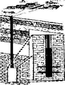
Matrix (low pressure) acidizing
The most important consideration in low pressure acidizing is that the well must be damaged, as low pressure acidizing is used primarily to increase well permeability by removing severe plugging in sandstone and carbonate formations. This type of treatment dissolves clays and other blocking materials. Low pressure acidizing is generally used in sandstone formations because they are more susceptible to damage. There are two types of low pressure acidizing:
1. wellbore clean-up, which essentially is the placement of an acid solution into the wellbore for a given time, allowing the acid to soak into the formation;
2. is the procedure of injecting an acid solution into the wellbore below the fracturing point.
1. Wellbore Clean-up consists basically of filling up the bottom of a wellbore with an acid solution and letting it soak into the formation. The acids used in this type of treatment require a long reaction time. Its primary use is to remove formation damage in and around the bottom of the wellbore.
 |
I ) the wellbore is preflushed prior to a wellbore clean-up, as the perforation zone must be free of any plugging in order to maximize the effect of the acidizing treatment;
2) an acid solution is then placed at the bottom of the wellbore and left to soak for a period of time;
3) after the soaking process is completed, the acid solution is flushed out of the wellbore and production is resumed.
2. Matrix acidizing involves the injection of an acidizing fluid at less than fracturing pressure into the bottom of the wellbore. The primary objective of matrix acidizing is to remove nay blockage material to restore or enhance permeability in limestones. It is generally used in a variety of situations, including: the removal of wellbore damage caused by drilling, completion, workover and well killing fluids or by the precipitation of deposits from produced water. This is especially applied if formation damage is present near a water zone or a gas cap.
|
|

|
|


 | |||
 | |||
|


1. Preflush – before matrix acidizing, the wellbore is preflushed so the perforation zone is free of any plugging to maximize the effects of the acidizing treatment.
2. Initial injection – the treatment is initiated by injecting the selected acid solution into the wellbore at a pressure below the fracture point.
3. Extension - the newly created channels are extended by the continued injection of acid under pressure (below the fracture point)
4. Post-flush – after acidizing treatment has been completed, the acid solution is flushed out of the wellbore and the production is resumed.

Perforation (oil well)
A perforation in the context of oil wells, refers to a hole punched in the casing or liner of an oil well to connect it to the reservoir. In cased hole completions, the well will be drilled down past the section of the formation desired for production and will have casing or a liner run in separating the formation from the well bore. The final stage of the completion will involve running in perforating guns, a string of shaped charges, down to the desired depth and firing them to perforate the casing or liner. A typical perforating gun can carry many dozens of charges.
Commonly, perforation guns are run on E-line as it is traditional to use electrical signals from the surface to fire the guns. In more highly deviated wells, coiled tubing may be used. Newer technologies allow the guns to be run on slickline. No communication with the surface is possible with slickline. Instead, a mechanism on the gun arms the charges upon reaching a certain temperature and pressure. A timer will then fire them following a set interval.
The benefit of this strategy is greater deal of control of the well. Casing the bottom of the hole allows the well to be completed without having to worry about reservoir fluids. It also allows precise selection of where in the formation production will be and to be able to seal off perforations, which are no longer useful or counterproductive, through cementing or straddling.
The disadvantage is that perforating can lead to "skin damage", where debris from the perforations can hinder productivity of the well. In order to mitigate this, perforating is commonly done underbalanced (lower pressure in the well bore than in the formation) as the higher formation pressure will caused a surge of fluids into the well at the point of perforating, hopefully carrying the debris with it. Other methods of stimulation such as acidising and propellent fracturing are often required to overcome this damage and bring the well up to its full potential.
Casing and perforating as a method of completion is common place nowadays, though in some unconsolidated formations, prone to production of sand, open hole completions, using only sandscreens, may be the preferred choice.
| |
Дата добавления: 2019-01-14; просмотров: 284; Мы поможем в написании вашей работы! |

Мы поможем в написании ваших работ!