The order of performance of work
LABORATORY WORK № 1
Investigation of linear electric DC circuits using Ohm and Kirchhoff's laws
The purpose of the work:to carry out an experimental verification of the laws of Ohm and Kirchhoff in linear electric circuits of direct current, to learn how to build and analyze graphs of potential diagrams.
Brief Theory
Ohm's law. Ohm's law is a fundamental law of electrical engineering. It establishes a connection between current and voltage.
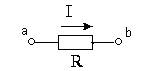
1 Ohm's law for the passive part of the chain:

Current on the circuit without EDS. is directly proportional to the voltage at the ends of this section and inversely proportional to its resistance.
2 Ohm's law for the active part of the chain:

where EMF E is taken with the sign "+" if its direction coincides with the direction of the current, and with the sign "", if the EMF E is directed against the current.
Ohm's law for the simplest electrical circuit
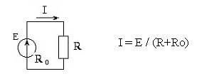
where R is the external resistance of the circuit
R0 is the internal resistance of the source
I Kirchhoff's law is a consequence of the law of conservation of charge. It is formulated for the node: "The algebraic sum of currents at the node is zero":

The currents entering and leaving the node have different signs.
For example, for node "a" we have: I1 + I2-I3 = 0. (The currents entering the node, we took with the sign "+", and leaving the node - with the sign "-".)

II Kirchhoff's law is a consequence of the law of conservation of energy. It is formulated for a closed loop: "The algebraic sum of the emf acting in the circuit is equal to the algebraic sum of the voltage drops in this circuit":

In order to write down Kirchhoff's II law, it is necessary to select arbitrarily the direction of circuit bypass. If the directions E and I coincide with the direction of circuit bypass, then they are taken positive, otherwise they are negative.
For example, for an external circuit, we have:
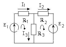
E1-E2=I1R1+I2R2.
A potential diagram is a graph of the distribution of the potential of an electrical circuit against the resistance of the sections of this circuit:. To construct a potential diagram, the potential of any point is equated to zero (grounded) and the potentials of the remaining points are determined as the voltage between the given point and the zero potential point. On the abscissa, the resistances of the sections of the chain are plotted with respect to the point of the zero potential, along the ordinate are the potentials of the points. In the diagram, the zero potential point is placed at the origin. The graph looks like a broken line.
|
|
|
When constructing a diagram, it is necessary to take into account that:
The source increases the potential by the amount of EMF in the direction of the source and reduces it by the same amount in the opposite direction;
The current in the section of the circuit with the resistance is directed towards the lowering of the potential;
The potentials of the initial and final points of the closed contour are zero.
The change in potential at different parts of the chain is illustrated in Table 1.
Table 1
| Circuit segment | Potential changes |

| 
|

| 
|
| 
|

| 
|

 -internal source resistance -internal source resistance
| 
|
The graph of the potential diagram allows you to determine the voltage between any points of the circuit; find points of equal potential; by the angle of inclination of the lines to judge the strength of the current in different sections. An example of constructing a potential diagram is shown in Figure 1.
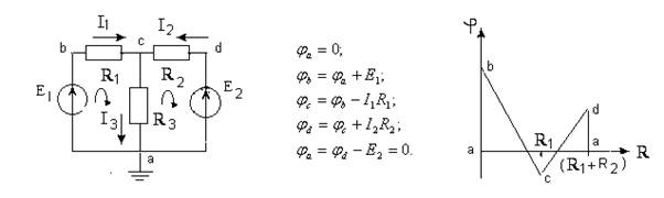
Figure 1
The order of performance of work
● Assemble the chain (figure 2). As sources E1 and E2 take unregulated and regulated sources of DC voltage (E1 = 15 V, E2 = 5 ÷ 15 V).

Figure 2
● Measure the EMF, currents and voltages on individual sections of the circuit. Record the measurement results in Table 2.
table 2
| E1, V | E2, V | I1, mA | I2, mA | I3, mA | U R1, V | UR2, V | U R3, V | U R4, V | U R5, V |
|
|
|
● Draw equations for I and II of Kirchhoff's laws. Check the implementation of these laws.
● Measure the potentials of all points in the circuit by taking the potential of one of them equal to zero, grounding it (φ1 = 0). Record the measurement results in
Table 3
| φ | φ1 | φ2 | φ3 | φ4 | φ5 | φ 6 | φ1 |
| φизм | 0 | 0 | |||||
| φрасч. | 0 |
● Calculate the potentials of these points and construct the calculated and experimental potential diagrams for the outline of the circuit.
Control questions and tasks:
1 Define the node, branch, path.
2 How can you determine the number of currents in a complex electrical circuit?
3 Formulate the laws of Ohm and Kirchhoff.
4 What does the potential diagram show along the circuit of the electrical circuit?
5 What are the features of constructing a potential diagram?
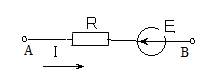
6 Find the potential at point "B" if the potential at point "A" is 15 V, R = 10 Ohm, I = 2 A, E = 5 V.
Дата добавления: 2018-04-15; просмотров: 197; Мы поможем в написании вашей работы! |

Мы поможем в написании ваших работ!