Figure 9.2(a) Oxygen indicator — circuit diagram
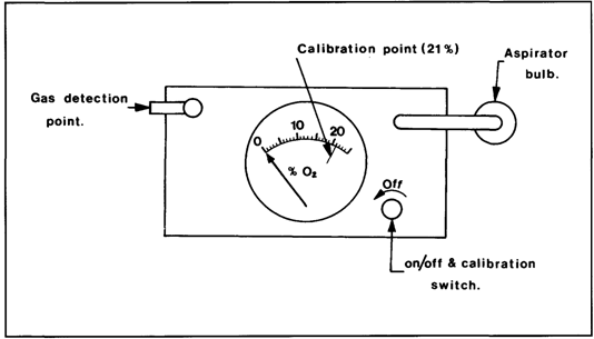
Figure 9.2(b) Oxygen indicator — plan view
A schematic diagram of the polarographic cell used in some oxygen analysers is shown in Figure 9.2(c). In this cell, the current is controlled by the electrochemical reaction of oxygen at the cathode (the permeable membrane). The life of the cell is approximately six months when continuously operated in air.

Figure 9.2(c) A polarographic cell
These instruments should be regularly spanned (calibrated) with fresh air (21 per cent oxygen) and test-nitrogen (a virtual zero per cent oxygen content). Liquid contamination, pressure or temperature effects may result in drifting of instrument response.
9.7.3 Combustible gas indicators
Catalytic instruments
The basic electric circuit (Wheatstone Bridge) of the combustible gas indicator is shown in Figure 9.3(a). The gas to be measured is aspirated over the sensor filament which is heated by the bridge current. Even though the gas sample may be below the lower flammable limit, it will burn catalytically on the filament surface. In so doing, it will raise the temperature of the filament, increase its electrical resistance and unbalance the bridge. The resultant imbalance registers on the meter which indicates the hydrocarbon content in the air.
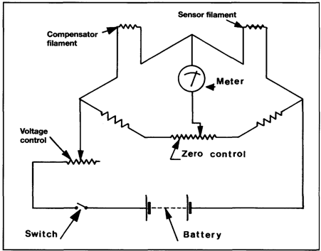
Figure 9.3(a) Combustible gas indicator — circuit diagram
Such instruments are designed principally to indicate flammability but are also used to detect the presence of small concentrations of gases in air.
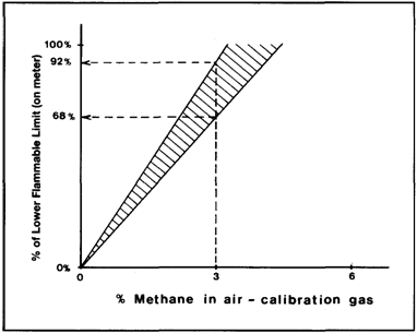
The meter scale commonly reads from zero per cent to 100 per cent of the lower flammable limit (LFL). On instruments having a dual range, a second scale indicates zero to 10 per cent of the LFL. Instruments of this type contain batteries which must be checked prior to use and it is a recommended practice to check the instrument using a calibration gas at frequent intervals. When calibrating the instrument, the meter reading should fall within the range indicated on the calibration graph which is provided by the manufacturers — see Figure 9.3(b).
In the example shown in Figure 9.3(b), a meter reading of between 68 and 92 per cent of LFL for a calibration gas containing three per cent methane in air indicates that the detector filament is in good order. These values are only given for illustration and reference must always be made to the graphs which accompany each calibration kit.
Tank spaces being sampled which have an atmosphere above the flammable range will produce a low or even zero reading on this type of meter. However, as the sample is initially drawn into the meter, the meter needle will give a momentary strong deflection before returning to its steady low or zero reading. This momentary deflection must always be watched for, since it gives warning that the following steady
Дата добавления: 2018-02-28; просмотров: 427; Мы поможем в написании вашей работы! |

Мы поможем в написании ваших работ!