Table 8.1 ASTM 56 (short table)
| * Density at 15°C (Kg/L) | Factor for converting Weight in Vacuo to Weight in Air | Density at 15°C (Kg/L) | Factor for converting Weight in Air to Weight in Vacuo |
| 0.5000 to 0.5191 | 0.99775 | 0.5000 to 0.5201 | 1.00225 |
| 0.5192 to 0.5421 | 0.99785 | 0.5205 to 0.5432 | 1.00215 |
| 0.5422 to 0.5673 | 0.99795 | 0.5433 to 0.5684 | 1.00205 |
| 0.5674 to 0.5950 | 0.99805 | 0.5685 to 0.5960 | 1.00195 |
| 0.5951 to 0.6255 | 0.99815 | 0.5961 to 0.6265 | 1.00185 |
| 0.6256 to 0.6593 | 0.99825 | 0.6266 to 0.6603 | 1.00175 |
| 0.6594 to 0.6970 | 0.99835 | 0.6604 to 0.6980 | 1.00165 |
| 0.6971 to 0.7392 | 0.99845 | 0.6981 to 0.7402 | 1.00155 |
| 0.7393 to 0.7869 | 0.99855 | 0.7403 to 0.7879 | 1.00145 |
| 0.7870100.8411 | 0.99865 | 0.7880 to 0.8421 | 1.00135 |
| 0.8412 to 0.9034 | 0.99875 | 0.8422 to 0.9044 | 1.00125 |
| 0.9035 to 0.9756 | 0.99885 | 0.9045 to 0.9766 | 1.00115 |
| 0.9757 to 1.0604 | 0.99895 | 0.976710 1.0614 | 1.00105 |
| 1.060510 1.1000 | 0.99905 | 1.061510 1.1000 | 1.00095 |
8.1.6 LNG quantification
The foregoing discussion has been general in nature and applies to all liquefied gases. LNG trading, however, differs from other liquefied gas trading in two respects affecting cargo quantification. Firstly, LNG is traded within long-term projects with dedicated production, transportation and reception facilities. Secondly, cargo boil-off during loaded and ballast voyages is used as ship's fuel. Accordingly, commercial cargo quantification is tailored to the particular project and contract and this is usually on the basis of calorific value of cargo delivered. Calorific value is derived from a knowledge of cargo composition and the mass of the liquid transferred, with an adjustment made for the calorific content of the volume of the vapour displaced. Thus, weight-in-air is not involved in the quantification of LNG cargoes and mass is invariably calculated from liquid volume and density at tank conditions.
8.1.7 Shore measurement versus ship measurement
Terminals usually require storage tanks to be measured for day-to-day internal accounting. However, shore tank measurements for cargo loaded or received are not always as accurate as ship measurements.
Firstly, shore storage tanks usually have greater cross-sections than the ship's tanks. Therefore, there can be greater inaccuracies associated with on-shore liquid level measurement, particularly in the transfer of small cargoes.
More important is the question of vapour flow to and from a shore tank during cargo handling. When loading a ship, in order to maintain shore tank pressure within pressure limits, vapour flow may be from other shore storage tanks, from liquid vaporisers or from the ship-to-shore vapour return line. Similarly, during ship discharge, vapour flow may be from the shore tank to other shore tanks, to the shore reliquefaction plant or to the ship by the shore-to-ship vapour return line. In cases where there is only one shore tank, the liquid input to the tank from production run-down must also be considered. These factors add to uncertainty in shore tank measurement. It is, therefore, common practice to use the ship's figures to determine cargo volumes for
custody transfer at both loading and receiving terminals. Because of this, some customs authorities require the ship's tank calibration tables to be certified by an approved classification society or by suitable independent cargo surveyors.
On loading, it is important to take account of the density of the liquid heel in each ship's tank. If this is appreciably different from the density of the cargo to be loaded, then, the density of the liquid in the ship's tanks after loading may be significantly affected.
It is usual for cargo interests to appoint an independent cargo surveyor as an unbiased third party to verify the ship and shore volume measurements, the use of appropriate density values and the cargo calculations.
8.2 MEASUREMENT OF CARGO TANK VOLUMES
All ships are provided with a calibration table for each cargo tank. The calibration table enables liquid and vapour volumes to be found from a measurement of the liquid level. A calibration table is obtained from careful measurements taken at ambient temperature and pressure after the ship is built. The volumes given in the tables normally assume the ship to be upright and with no trim. The calibration tables, therefore, contain correction factors with which to adjust the liquid level measurements in accordance with the actual conditions of the ship's list and trim and with the cargo tank temperatures at the time of cargo measurement.
The principal corrections are described below.
8.2.1 Trim correction
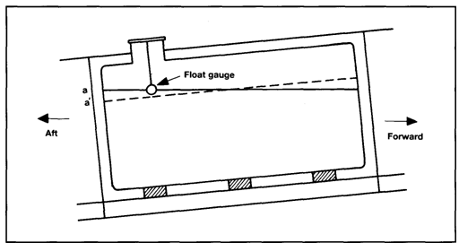
Figure 8.1 shows a prismatic tank on a ship which is trimmed by the stern. In other words the ship's aft draft is greater than the forward draft. As can be seen, with the ship in the trimmed position, the liquid level in the tank remains horizontal and the liquid level rises by the amount a/a' at the aft bulkhead. However, if the ship was on an even keel (or zero trim), the liquid level would be as shown by the dashed line on the diagram.

Дата добавления: 2018-02-28; просмотров: 1172; Мы поможем в написании вашей работы! |

Мы поможем в написании ваших работ!
