Figure 5.18 Flow diagram for reliquefaction within an LPG terminal
Compressors for LPG terminal refrigeration are of a similar design to those outlined in 4.6 for LPG ships' reliquefaction systems but, generally, they have considerably greater capacity so that they can handle ship discharge or production run-down rates. A separate smaller capacity compressor is provided to handle boil-off vapours from within the shore tanks between loadings. Such boil-off may be generated as a consequence of heat input through the tank insulation.
Product condensers are either air-cooled or water-cooled, depending on economics and environmental aspects. Other heat exchangers may include units for warming refrigerated cargoes in order to load fully pressurised ships. Such equipment is often heated with glycol/water systems.
At some refrigerated terminals, it is common practice to receive refrigerated cargoes and subsequently to back-load fully pressurised ships. To facilitate loading operations, cargo heaters are often fitted in the terminal loading lines. These heaters are of the normal shell and tube design and sea water can be used as the heating medium. To carry out such operations without terminal heat exchangers requires the ship to be fitted with its own cargo heater of similar design.
Figure 5.18 shows a typical LPG terminal pipeline diagram. It includes tankage, reliquefaction plant and export pumps.
Figure 5.19 shows a typical LNG receiving terminal. This terminal utilises the gas in two ways:
• Gas is sent out to domestic and business consumers via the distribution main.
• There is a direct connections to an adjacent electric power station.
Gas vaporisation is achieved by:—
• Natural boil-off.
• Two types of vaporiser (open rack-type heated by sea water and submerged combustion-type heated by gas flame).
• Utilisation of cold energy in an adjacent air separation plant.

Figure 5.19 LNG receiving terminal — vaporiser/sendout
Other features are:—
• LNG is pumped from the in-ground storage tanks using submerged pumps.
• The pressure is raised to send-out pressure by a booster pump which is positioned before the vaporisers.
• Send-out gas is odorised and its calorific value is adjusted by injection of nitrogen or propane before leaving the plant.
Such terminals utilise the energy released by vaporisation in other ways. For example, to operate food freezer plants or to operate a direct expansion cryogenic generator to produce electricity.
5.4 INSTRUMENTATION
5.4.1 Product metering
The quantity of liquefied gas loaded onto a gas carrier can be determined by conventional tank gauging (ship and shore where appropriate) in the usual manner.
Alternatively, the volumes transferred can be monitored by flow meter. It should be noted, however, that where vapours are returned to the tank being discharged, the quantity of such vapours must also be taken into account in the calculation.
There are seven types of metering systems in regular use at liquefied gas terminals. These are listed below:—
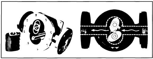
• Positive displacement meters operating in a similar manner to positive displacement pumps.
• Turbine meters where the rotation of the blades is proportional to the flow.
• Coriolis metering where the fluid is passed through a vibrating U-tube, the mass gas flow being determined from the twisting of the U-tube caused by the Coriolis effect.
• Ultrasonic metering whereby the volumetric flow rate can be determined. These meters are normally used for the measurement of vapour quantity.
• Vortex meter may be thought as an obstruction within the pipe which causes vortices to be generated on each side of the obstruction.
While the two former units require equipment to be fitted within pipelines, it is interesting to note that the others are non-intrusive.
The positive displacement, turbine, vortex, ultrasonic and coriolis types are covered in more detail below.

Дата добавления: 2018-02-28; просмотров: 1129; Мы поможем в написании вашей работы! |

Мы поможем в написании ваших работ!
