Figure 4.2 Pilot-operated relief valve
Adjustable settings for pilot-operated relief valves are used mainly in two different roles. Firstly, they may be used to provide a set pressure (not exceeding the MARVS) but higher than normal. This is known as the harbour setting. Secondly, on Type 'C' tanks, they can be adjusted to permit a means of reducing the MARVS to comply with United States Coast Guard (USCG) regulations. These regulations impose more stringent safety factors for pressure vessel design than do the Gas Code requirements.
Whenever such valves are used for more than one pressure setting, a proper record must be kept of changes to the pilot valve springs. The pilot assembly cap must always be resealed after such changes (see also 7.5) and this will ensure that no unauthorised adjustments can be made. When relief valve settings are changed, the high pressure alarm should be adjusted accordingly.
Cargo tank relief valves exhaust via the vent header. From there, the vapour is led to atmosphere via one or more vent risers. Vent riser drains should be provided. These drains should be checked regularly, to ensure no accumulation of rain water in the riser. Any accumulation of water has the effect of altering the relief valve operation due to increased back pressure.
Pressure relief valves on tanks require routine maintenance and for further information on this subject Reference 2.26 is recommended.
The Gas Codes require all pipelines which may be isolated, when full of liquid, to be provided with relief valves to allow for thermal expansion of the liquid. These valves usually exhaust back into cargo tanks. Alternatively, the exhaust may be taken to a vent riser via liquid collecting pots, in which case, means for detecting and disposing of liquid in the vent system must be provided.
4.2 CARGO PUMPS
Cargo pumps fitted on board refrigerated gas carriers are normally of centrifugal design and may be either of the deepwell or submerged type. They may operate alone or in parallel with one another. They may also operate in series with a deck-mounted booster pump and a cargo heater: this would happen during discharge of LPG to pressurised storage (see 4.3).
Some fully pressurised ships discharge cargo by pressurising tanks with vapour and booster pumps are fitted to speed the cargo transfer.
Pump performance curves
An understanding of pump performance is important when considering the work done by cargo pumps. Figure 4.3 shows a typical set of performance curves for a multistage deepwell pump (see also Figure 4.6).
The flow-head curve (Curve A)
Curve A shows the pump capacity, given in terms of flow rate (m3/hr), as a function of the head developed by the pump, given in terms of metres liquid column (mlc).
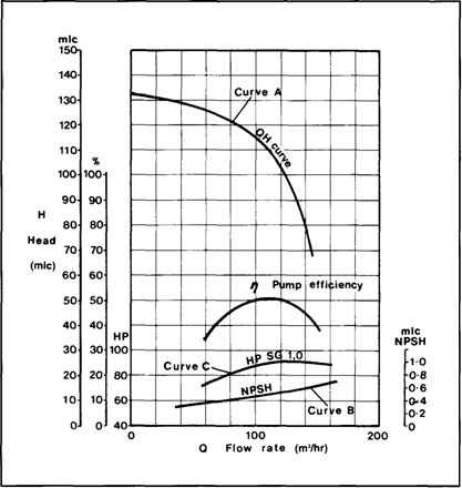
Figure 4.3 Pump performance curves — a deepwell pump
This curve is called thepump characteristic. By adopting metres liquid column and flow as the main criteria, the pump characteristic is the same, irrespective of the fluid being pumped. Taking curve A, shown in Figure 4.3; the pump will deliver 100 m3/hr against a head difference of 115 mlc between ship and shore tanks. To convert this head into pressure, the specific gravity of the cargo being pumped must be known.
For example, at a head of 105 mlc, the increase in pressure across the pump when pumping ammonia at -33°C with a specific gravity of 0.68 would be:
105 x 0.68 = 71.4 mlc (water) = 71.4/10.2 = 7 barg.
(Note:— the factor 10.2 in the foregoing equation denotes the height, in metres, of a water column maintained solely by atmospheric pressure — see Table 2.6.)
The net positive suction head curve (Curve B)
Curve B shows the Net Positive Suction Head (NPSH) requirement for the pump as a function of flow-rate. The NPSH requirement at any flow rate is the positive head of fluid required at the pump suction over and above the cargo's vapour pressure to prevent cavitation at the impeller. For example, at a capacity of 100 m7hr the NPSH requirement for the pump is 0.5 mic. This means that with a flow rate of 100 m7hr a minimum head of cargo equivalent to 0.5 metres is required at the pump suction to prevent cavitation. An over-pressure of 0.03 bar in the cargo tank is equivalent to 0.5 metres head when pumping ammonia at -33°C.
NPSH considerations are particularly significant when pumping liquefied gases because the fluid being pumped is always at its boiling point. It must be remembered that if cavitation is allowed to occur within a pump, not only will damage occur to the impeller but the shaft bearings themselves will be starved of cargo. This will restrict cooling and lubrication at the bearings and damage will quickly result.
Дата добавления: 2018-02-28; просмотров: 556; Мы поможем в написании вашей работы! |

Мы поможем в написании ваших работ!