Figure 3.2(b) Self-supporting prismatic Type 'B' tank
Type 'C' tanks
Type 'C' tanks are normally spherical or cylindrical pressure vessels having design pressures higher than 2 barg. The cylindrical vessels may be vertically or horizontally mounted. This type of containment system is always used for semi-pressurised and fully pressurised gas carriers. In the case of the semi-pressurised ships it can also be used for fully refrigerated carriage, provided appropriate low temperature steels are used in tank construction. Type 'C' tanks are designed and built to conventional pressure vessel codes and, as a result, can be subjected to accurate stress analysis. Furthermore, design stresses are kept low. Accordingly, no secondary barrier is required for Type 'C' tanks and the hold space can be filled with either inert gas or dry air.
In the case of a typical fully pressurised ship (where the cargo is carried at ambient temperature), the tanks may be designed for a maximum working pressure of about 18 barg. For a semi-pressurised ship the cargo tanks and associated equipment are designed for a working pressure of approximately 5 to 7 barg and a vacuum of 0.5 barg. Typically, the tank steels for the semi-pressurised ships are capable of withstanding carriage temperatures of -48°C for LPG or -104°C for ethylene. (Of course, an ethylene carrier may also be used to transport LPG.)
|
|
|
|
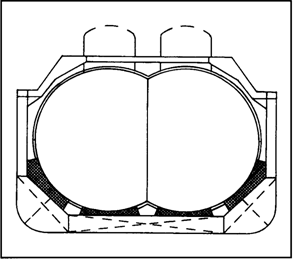
Figure 3.3 Type 'C' tanks — fully pressurised gas carrier
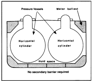
Figure 3.4 Type 'C' tanks — semi-pressurised gas carrier with bi-lobe tanks
Figure 3.3 shows Type 'C' tanks as fitted in a typical fully pressurised gas carrier. With such an arrangement there is comparatively poor utilisation of the hull volume;
however, this can be improved by using intersecting pressure vessels or bi-lobe type tanks which may be designed with a taper at the forward end of the ship. This is a common arrangement in semi-pressurised ships as shown in Figure 3.4.
3.2.2 Membrane tanks (membrane - 0.7 to 1.5 mm thick)
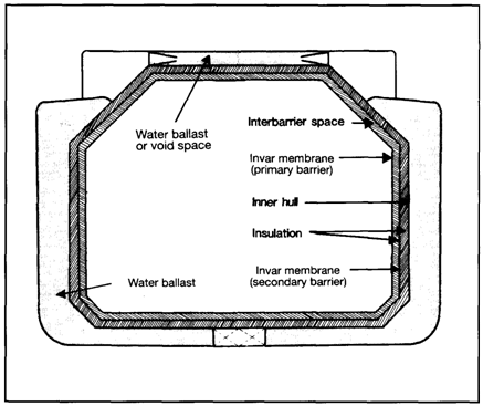
The concept of the membrane containment system is based on a very thin primary barrier (membrane - 0.7 to 1.5 mm thick) which is supported through the insulation. Such tanks are not self-supporting like the independent tanks outlined in 3.2.1; an inner hull forms the load bearing structure. Membrane containment systems must
always be provided with a secondary barrier to ensure the integrity of the total system in the event of primary barrier leakage. The membrane is designed in such a way that thermal expansion or contraction is compensated without over-stressing the membrane itself. There are two principal types of membrane system in common use — both named after the companies who developed them and both designed primarily for the carriage of LNG.
These two companies have now combined into one and future developments can be expected.
Gaz Transport membrane system
Figures 3.5(a) and 3.5(b) show the Gaz Transport system comprising a thin Invar primary barrier. Invar is a stainless steel alloy containing about 36 per cent nickel and 0.2 per cent carbon. This is attached to the inner (cold) surface of perlite-filled plywood boxes used as primary insulation. These boxes have thickness of between 200 and 300 millimetres. These, in turn, are attached to an identical inner layer of Invar (the secondary barrier) and, finally, a further set of similar perlite-filled boxes is used
Дата добавления: 2018-02-28; просмотров: 445; Мы поможем в написании вашей работы! |

Мы поможем в написании ваших работ!