By method of rotation or drilling method
- no rotation includes direct push rigs and most service rigs
- rotary table - rotation is achieved by turning a square or hexagonal pipe (the kelly) at drill floor level.
- top-drive - rotation and circulation is done at the top of the drillstring, on a motor that moves along the derrick.
- sonic - uses primarily vibratory energy to advance the drill string
By position of derrick
- conventional - derrick is vertical
- slant - derrick is at an angle (this is used to achieve deviation without an expensive downhole motor)
Rigging Up
Once the contractor gets the rig to the site, the next step is for the drilling crew to put the rig together, or rig up. For land rigs, the crew first brings in the rig's substructure.
SUBSTRUCTURES
A substructure is a framework that rests right over the hole. The substructure raises the rig floor anywhere from about 10 to 40 feet (3 to 12 metres) above the ground. The rig floor is the work area for the drilling crew. With the rig floor elevated above ground level, room is available under the rig for the special high-pressure valves and other equipment that the crew connects to the top of the well's casing. The exact height of a substructure depends on the space needed to clear this equipment. Remember, too, that, in some cases, a cellar provides more space for the equipment.
One type of substructure is the box-on-box (Fig. ). Using trucks or portable cranes, the crew stacks one steel-frame box on top of another to achieve the desired height. Another substructure is the self-elevating, or slingshot, type. Crew members place it on.

Fig. This rig rests on a box-on-box substructure.
RIG FLOOR
Crew members set many pieces of equipment on the substructure, including a steel-and-wood rig floor on which to work. An important piece of equipment on the rig floor is the drawworks. Inside this large hoist is a spool, or drum, on which the crew wraps braided steel cable called wire rope or drilling line. The drawworks, the drilling line, and the mast or derrick support practically everything that goes in or comes out of the hole.
RAISING THE MAST OR DERRICK
Crew members next raise the mast or derrick. If the rig has a mast, they raise it from horizontal to vertical with the drawworks . If the rig has a derrick, crew members bolt it together, one piece at a time, on the substructure. After finishing the well, they have to disassemble the derrick and rebuild it at a new site. When assembled, a derrick looks very much like a mast. Unlike a mast, however, which the crew raises or lowers as a complete unit from a pivot point in the substructure, a derrick has four legs that extend from each corner of the substructure.
Derricks get their name from a hangman who plied his trade in Tyburn, England, in the 1600s. Even though Derick's first name is unknown, his gallows were so distinctive that everyone began calling any towerlike structure with cross braces and girders a "derick." By the nineteenth century, scholars had added the extra "R."
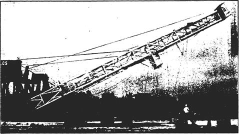
Fig. A mast is raised from horizontalto vertical position.
MASTS
Crew members can raise or lower a mast without completely assembling and disassembling it each time the rig moves. Not having to build and take apart a derrick is a timesaving advantage. Once the manufacturer constructs all the braces, girders, and cross members of a mast, no one totally disassembles it again until the contractor scraps it.
Some masts fold, telescope, or even come apart into sections to make them shorter and easier to move. Nevertheless, they retain their integrity as a unitized component. Virtually every land rig has a mast; about the only place you can find a true derrick is offshore.
DERRICKS
Some offshore platforms have derricks because they allow the crew to drill several wells right next to each other on the platform. The structure that holds the crown block in a derrick is so large that the crew can shift the crown block's position within the top of the derrick. With a corresponding shift in the rotary table's position on the rig floor, so that it centers directly under the crown block, crew members can drill one well, shift the crown block and the rotary, drill another well, shift the crown block and the rotary again, drill still another well, and so on, until they have drilled up to nine wells. At this point, they can drill even more wells on the platform by moving the derrick to another position on the deck and starting the process over.
DERRICK AND MAST HEIGHTS
A derrick or mast is a tall and strong tower that supports the entire weight of the drill string and other tools that the crew runs in and out of the hole. The drill string may be thousands of feet long. To pull the string, the crew has to unscrew it, or break it out, into smaller lengths, or stands. Crew members set each stand back in the derrick or mast in the vertical position after they pull it. The tallest derricks and masts are about 200 feet, or 60 metres, high. The shortest are about 65 feet, or 20 metres, high.
As mentioned before, a derrick (usually called a "standard derrick") is a structural tower that a crew assembles piece by piece. Practically everyone in the drilling business, however, calls a mast a derrick regardless of what it really is. This book will do the same.
A derrick's height governs whether the crew pulls pipe from the hole in singles, doubles, or thribbles. If crew members "pull singles," they break out the pipe a single joint at a time. A single length, or joint, of drill pipe is about 30 feet, or 9 metres, long. If they pull doubles, they break out the pipe in two-joint stands of about 60 feet, or 18 metres. If they pull thribbles, they break out the pipe in three-joint stands of about 90 feet, or 27 metres. In rare instances, they may pull fourbles, in which case they break out the pipe in four-joint stands of about 120 feet, or 36 metres. In any case, the longer the stand, the faster the crew can pull the pipe and return it to the hole.
A derrick is one of the most distinctive things about a drilling rig. You can easily see it from a distance. The driller needs enough height to lift the pipe stands well above the rig floor. Not every derrick is as tall as 200 feet, or 60 metres, but even shorter ones stand out from a flat landscape.
DERRICK LOAD RATING
Derricks have to be strong and portable. Manufacturers of derricks rate their products by the vertical load they can carry and by the amount of wind they can withstand. Derrick capacities for vertical loads run from 0.25 million up to 1.5 million pounds (over 0.5 million to about 3 million kilograms). In some cases, the drill string alone may weigh as much as a half million pounds, or over one million kilograms. Most derricks can withstand winds of 100 to 130 miles per hour, or 160 to 210 kilometres per hour.
Rig Components
A rotary rig's main job is to make hole. To make hole, the drilling crew places a bit on bottom, then the driller rotates it and pumps drilling mud to it. A rig needs a multitude of equipment to make these operations happen. A first look at all the gear on a drilling rig can overwhelm you. It is, however, easy to understand a rig's components if you divide them into systems: power, hoisting, rotating, and circulating.
Power System
Without power nothing on a rig operates. Machinery must have an energy source to make it go. On virtually every drilling rig, the power comes from internal-combustion engines, which are called prime movers. Further, they often use diesel fuel. Because of the way diesel engines operate, they deliver more turning force, or torque, than gasoline engines. As a result, many industries, including the drilling industry, use diesels.
A rig may need from two to four prime movers, depending on its size. The bigger the rig, the deeper it can drill and the more power it needs. Thus, big rigs have three or four prime movers. Together, they develop 4,500 horsepower (about 3,300 kilowatts) or more. In comparison, a powerful car engine may put out only 300 horsepower (220 kilowatts) or so; most develop even less.
This power must be transferred to the rig's components to make them work. For example, at the same time as the rotary table needs power to turn the bit, the mud pump needs power to circulate drilling mud. What is more, to provide maximum power to a component, the driller must also be able to combine the power of two or more engines. Two common methods transfer power on today's rigs and allow the driller to combine engine power: mechanical transmission and electrical transmission.

Fig. Multiengine and chain-drive compound
| internal-combustion engine | двигатель внутреннего сгорания |
| prime mover | |
| turning force( torque) | момент вращения |
| horsepower (hp) | киловатт |
| transfer to | |
| mechanical transmission | |
| electrical transmission | |
| chain-drive compound | |
| sprocket | |
| transmission chain | |
| brakes | |
| auxiliary brakes | |
| transmit power to | передавать энергию чему-л |
| цепь | |
HOISTING SYSTEM
Both mechanical and electrical rigs need a hoisting system. The hoisting system consists of the drawworks, the derrick, the crown block, the traveling block, and wire rope drilling line. The drawworks has a drum on which the crew wraps, or spools, drilling line. The drilling line goes from the drawworks to several pulleys, or sheaves (pronounced "shivs"), in the crown block. Drilling line also runs through sheaves in the traveling block. The crew hangs drill pipe and other equipment from a hook on the traveling block. The derrick supports the traveling block and the drilling hook. By taking in or letting out the drilling line on the drawworks, the driller raises and lowers the hook and traveling block.
DRAWWORKS
The drawworks is one of the largest and heaviest pieces of equipment on a rig. It has a spool-shaped revolving drum around which crew members wrap the wire rope they call drilling line. It also has several shafts, clutches, brakes, and chain-and-gear drives. The shafts, clutches, and drives allow the driller to engage and disengage equipment on the drawworks. The driller can also change the speed with which the drum revolves, thereby varying the speed with which the drawworks raises the traveling block and hook. The driller controls the drawworks from a panel, or console, near the drawworks.
The drawworks also has a heavy-duty main brake. Large bands on both rims of the drum stop the drum from turning when the driller engages the brake. When the brake is disengaged, the drawworks drum lets out drilling line to lower the traveling block. An auxiliary hydraulic or electric brake assists the main brake when the draw-works is raising or lowering heavy loads. The auxiliary brake absorbs some of the momentum created by a heavy load. The main brake thereby works more efficiently.
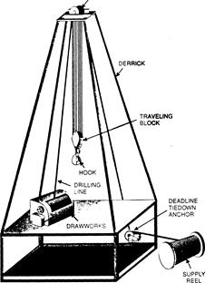
Fig. The hoisting system
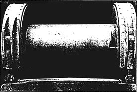
Fig. The drawworks brake has two large bands on each end of the drawworks drum
CATHEADS
A cathead is a winch, or windlass, on which a line, such as rope, cable, or chain, is coiled. When activated, the cathead reels in the line with great force. Pulling on a rope, cable, or chain is vital to screwing and unscrewing (making up and breaking out) drill pipe.
A catshaft runs across the top of the drawworks and sticks out on both sides of it. It is powered by the drawworks motor or compound and turns when the drawworks is powered up. The manufacturer installs a friction cathead on each end of the catshaft. Just inboard of the friction catheads, and on the same catshaft, the manufacturer also mounts a mechanical, or automatic, cathead. A drawworks thus has four catheads: a friction cathead at each end of the cat-shaft and an automatic cathead inward from each friction cathead.
A friction cathead is a steel spool a foot (30 centimetres) or so in diameter. It revolves as the catshaft revolves. Crew members used to employ friction catheads and a length of catline—a large-diameter rope made out of plant fiber, or hemp—to move heavy equipment around the rig floor. One floorhand rigged up one end of the catline to the object they wished to move. Another wrapped the other end of the catline a couple of times around the cathead. (Rig hands called this operation "taking wraps around the cathead.") This second crew member gripped the line near the turning cathead and, by pulling hard or not so hard on the line, adjusted the amount of friction the cathead applied to the line. When the crew member tightened the line—applied more friction—on the cathead, the cathead pulled on the catline and lifted the object. When the crew member loosened the catline wraps on the cathead— released the friction—the cathead stopped pulling on the catline.
.An automatic cathead also pulls on a wire rope or, in some cases, on a chain, but in a way very different from a friction cathead. Instead of having to manually adjust tension on a line, the driller simply moves a control lever on the console to engage or disengage an automatic cathead. When engaged, an automatic cathead pulls on a wire rope or chain to make up or break out the drill string when the crew is running it in or out of the hole. The driller also uses it when the crew is adding a joint of pipe to the drill string as the hole deepens.
The automatic cathead on the driller's side of the drawworks is the makeup cathead. As stated earlier, the manufacturer mounts it inward from the friction cathead. A chain like the chain you use to keep your dog tied up, only stronger, runs to the makeup tongs. A rotary helper latches the tongs around the pipe. When the driller starts the makeup cathead, it spools in the chain. Continued pull by the cathead on the chain makes the tongs tighten the pipe joint.
The automatic cathead on the opposite side of the drawworks is the breakout cathead, which looks exactly like the makeup cathead. The driller engages it to take apart, or break out, pipe. Just as the makeup cathead pulls on the makeup tongs to tighten and make up pipe, the breakout cathead pulls on the tongs to loosen and break out pipe. Usually, however, wire rope instead of a chain is used on the breakout cathead. You'll see why in the next section. For now, just remember that it has to do with the way in which the crew makes up and breaks out pipe.
BLOCKS AND DRILLING LINE
Drilling line is wireline, or wire rope. Drilling line is, however, considerably larger than the wire rope on the tongs. Wire rope is what most of the world calls cable. Wire rope manufacturers make drilling line by braiding several steel wires together. It looks like cloth, or fiber, rope except that it is made from steel wire rather than plant or plastic fibers. Drilling line ranges in diameter from ¾ to 2 inches, or about 22 to 51 millimetres.
First, assume that the derrick is lying horizontally in its cradle in the substructure. The drawworks is on the rig floor and the rig's engines are running. To begin, workers take one end of the rope off the supply reel, which is resting on the ground near the substructure. They pull the line from the reel to the top of the derrick. There the rig builders installed a large set of pulleys, or sheaves, termed the crown block. Crown blocks have several sheaves over which workers string the drilling line. They thread, or reeve, the drilling line over a groove in a crown block sheave. Then they pull the end of the line to another set of sheaves placed near the middle of the derrick. This sheave set is the trav eling block.
The driller raises and lowers the traveling block in the derrick as drilling progresses. During string-up, however, the traveling block is also stationary until workers complete the string-up job. To continue stringing up, they reeve the end of the drilling line through one of the traveling block sheaves. Then they pull the line back to the crown block. They reeve the line over another sheave in the crown block and pull it back to the traveling block. There, they reeve the line through another traveling block sheave and pull it back to the crown.
The number of times the workers reeve the line through the blocks depends on the weight the line has to support and on the size of the crown and traveling blocks. Crown blocks and traveling blocks vary in the size and the number of sheaves they contain.
After the workers reeve the line for the last time over the crown block sheaves, they pull the end of the line to the drawworks. They secure the end of the drilling line to the drum in the drawworks. A worker then powers up the drawworks and takes several wraps of line around the drum, much as an angler reels in fishing line after a cast. Since the traveling block is resting on a support that holds it stationary, the line runs through it without moving it. The part of the drilling line running from the drawworks to the crown block is the fastline . It moves when the rig is operating. That is, after the drilling crew readies the rig, the fastline moves on or off the drawworks drum when the driller raises or lowers the traveling block.

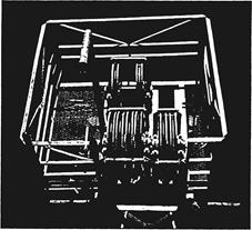
Fig. Several sheaves make up the crown block.

Fig The drilling line is also reeved several times though the traveling block's sheaves.
During the drilling of a well, the drilling line carries many tons of drill pipe and other tools in and out of the hole over a distance of several miles; or it uses many newtons of force moving drill pipe over a distance of thousands of metres. The crew therefore rates drilling line use in ton-miles or megajoules. (When a line has moved 1,000 newtons of load over a distance of 1,000 metres, the line has given i megajoule of service.) The driller keeps careful track of how many ton-miles (megajoules) of wear occur over time. By consulting specially prepared tables, the driller knows when it is time to slip the line. Slipping the line places unworn line on the wear points where the line goes through and over sheaves in the traveling and crown blocks. The drilling line also wears where it spools off the drawworks drum.
To slip the line, crew members first hang the traveling block in the derrick so that it cannot move, or they support the traveling block on the rig floor in an upright position. The crew then loosens the clamps on the deadline anchor.
The driller starts the drawworks and spools, or slips, the required length onto the drawworks drum. Since the traveling block is hanging in the derrick or standing on the rig floor so that it cannot move, and since the deadline clamps are loosened, the drilling line comes off the supply reel, slips through the traveling block's sheaves, and goes onto the drawworks drum.
The driller slips enough line—say 90 feet (25 metres) or so—to ensure that the wear points on the line change. Finally, the crew retightens the deadline anchor clamps, releases the traveling block, and returns to normal operations. After the driller and the crew slip the line a few times, it starts to accumulate on the drawworks drum. To prevent too much line from collecting on the drum, the crew cuts off excess line during the slipping operation.
| Hoisting system | |
| Lower \ raise (v) | |
| Drillsrting | |
| Derrick | |
| Block and tackle | |
| Drawworks | |
| Sheaves | |
| Traveling block | |
| Hook | |
| Load | |
ROTATING SYSTEM
Rotating equipment includes the devices that make the bit turn. On a conventional rig, the equipment consists of a swivel, an upper kelly cock, a special length of pipe called the kelly, a lower kelly cock, a kelly saver sub, the rotary table, the drill pipe, the drill collars, and the bit . Some contractors install a special system on their rigs called a top drive. It replaces many parts of the conventional rotating system; top drives are discussed in more detail later.
According to the American Petroleum Institute (api), all the pipe between the swivel and the bit, including the kelly, the drill pipe, and drill collars, is the drill stem. (The api is a trade association that sets oilfield standards and specifications.) The drill string includes only the drill pipe—not the kelly and the drill collars. Be aware, however, that practically everybody in the oil patch uses "drill string" to mean the drill pipe and the drill collars. This book will follow the same convention.
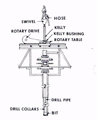
Fig. Schematic of rotary system
SWIVEL
The swivel is a remarkable device. It sustains the weight of the drill stem, permits it to rotate, and provides a passageway for drilling mud to get into the drill stem. The swivel also has a large bail, similar to the bail, or handle, on a bucket but much, much larger. The swivel's bail fits inside the hook at the bottom of the traveling block. Crew members also attach the rotary, or kelly, hose to the side of the swivel at the gooseneck. The gooseneck is a curved piece of erosion-resistant pipe on the swivel. Drilling mud enters the swivel through the rotary hose and the gooseneck.

Fig. The large bail of this swivel hangs from the hook of the traveling block.
KELLY
The crew makes up a length of pipe called the kelly on the bottom of the swivel. Mud passes through the kelly and into the drill string. A kelly is not round pipe. Instead, it has four or six flattened sides . No one knows exactly why it is called the kelly. At least two persons named Kelly, however, received patents on four-sided, or square, kellys around 1920. Before then, people called kellys "grief stems."
A four-sided kelly has a square cross section—that is, if you cut across the body of a four-sided kelly and look at it end on, it is square. A six-sided kelly has a hexagonal cross section. In general, a hexagonal kelly is stronger than a square kelly. As a result, contractors tend to use hexagonal kellys on large rigs to drill deep wells because extra strength is needed. Small rigs often use square kellys because they are less expensive. Manufacturers make most square and hexagonal kellys to api specifications. A standard api kelly is 40 feet (12.2 metres) long, although an optional length of 54 feet (16.5 metres) is also available. Most rigs use 40-foot kellys.

Fig. A square kelly
Fig. A hexagonal Kelly
Kellys are squareor hexagonal, instead of round, because the flat sides provide a way to make the kelly turn. The driller lowers the kelly inside a corresponding square or hexagonal opening in the kelly bushing. The kelly bushing fits into another rotating component called the master bushing. The master bushing fits inside the rotary table. Thus, as the rotary table rotates, the master bushing and the kelly bushing also rotate (fig. 73). Since the kelly mates with the kelly bushing, the kelly also rotates. The pipe rotates because the crew connects it to thebottom ofthe kelly. Finally, the drill collars and the bit rotate because the crew connects them to the drill pipe.
The kelly passes through the kelly bushing. The master bushing rotates the kelly bushing, which rotates the kelly. The drill pipe, drill collars, and bit rotate as well. They disappear into the rotary table where you can't see them. At the same time, the mud pump sends mud through the rotary hose and into the swivel. From the swivel, the mud flows inside and down the kelly, the drill pipe, the drill collars, and out the bit. The mud shoots out the bit and lifts cuttings up the hole to the surface.
ROTARY TABLE
The rotary table, of course, gives rotary drilling its name. The compound, a drive mechanism from the drawworks, or an electric motor powers the rotary table. The crew fits the master bushing into the rotary table. During normal drilling operations, the master bushing drives the kelly bushing. When drilling stops and the kelly bushing is out of the master bushing, the master bushing can hold the slips.. Slips have strong, toothlike gripping elements called dies.Slips fit around the drill string and suspend it in the hole. With the drill string suspended by the slips, the crew can remove the kelly and the swivel from the drill string. The traveling block and hook no longer suspend the drill string.
TOP DRIVE
As mentioned earlier, some rig owners replace the conventional swivel with a powered swivel called a top drive . The top-drive unit hangs from the traveling block's hook in place of a conventional swivel. A powerful heavy-duty motor in the top drive turns a threaded drive shaft. The crew stabs, or inserts, the unit's drive shaft directly into the top of the drill stem. When the driller starts the top drive's motor, it rotates the drill stem and the bit. The rig therefore does not use a conventional swivel, a kelly, a rotating rotary table and master bushing, or a kelly bushing. Rigs with a top drive still need, however, a rotary table and master bushing to provide a place for the slips to suspend the pipe.
The main advantage of a top drive over the conventional kelly and rotary system is that a top drive makes it safer and easier for crew members to handle the pipe. Because of the way in which a conventional rig operates, the crew can add only one joint of drill pipe at a time as the hole deepens. With a top-drive system, however, because it operates differently from the conventional system, the crew can add pipe three joints at a time, if they choose to do so. Adding three-joint stands of pipe saves time. A top-drive unit also makes making up or breaking out pipe safer. The crew uses the unit's built-in tongs to make up and break out pipe from the string.
The top-drive unit's motor provides makeup and breakout power, thus eliminating the need to use the conventional tongs and the catheads.

Fig . A top drive
DRILL STRING
The drill string consists of the drill pipe and special, heavy-walled pipe called drill collars. Manufacturers make most drill pipe from steel, but they also use aluminum. Drill collars, like drill pipe, are metal tubes through which the driller pumps drilling mud.
They are heavier than drill pipe, however. The drilling crew uses them to put weight on the bit to make it drill. They install them in the drill string below the drill pipe. The number of drill collars they install depends on how much weight the bit needs and on how much the drill collars weigh. The bigger a drill collar's outside diameter and the smaller its inside diameter, or the thicker its wall, the more it weighs.

Fig. Drill pipe and drill collars
One of the lightest drill collars has an outside diameter of 2 7/8 inches (73 millimetres) and an inside diameter of 1 ½inches (38 millimetres). This collar's wall thickness is 11/16 of an inch (17.5 a typical drill pipe joint does not, by the way, include the weight of the drill pipe's tool joints. Tool joints are threaded pieces on each end of the pipe . The pipe maker welds them to the pipe. The crew connects the pipe with the tool joints. Tool joints add a significant amount of weight to drill pipe, but not enough to make it weigh anywhere near as much as drill collars.
A typical drill pipe joint does not, by the way, include the weight of the drill pipe's tool joints. Tool joints are threaded pieces on each end of the pipe. The pipe maker welds them to the pipe. The crew connects the pipe with the tool joints. Tool joints add a significant amount of weight to drill pipe, but not enough to make it weigh anywhere near as much as drill collars.
Eventually, to reduce the number of tool joints and connections in the drill string, manufacturers offered range 2 pipe. Finally, as derrick heights increased, pipe makers began selling range 3 lengths to reduce the number of connections even more. Today, however, range 2 pipe is still the most popular length. Because contractors widely use range 2 lengths of drill pipe. Most people simply say that a joint of drill pipe is about 30 feet long and that a three-joint stand (a thribble) is 90 feet long. This book uses the same convention.
Tool joints give drill pipe a characteristic bulge at each end. One tool joint has female, or inside, threads. The female end is the box. The tool joint on the other end has male, or outside, threads. The male end is the pin. To make up drill pipe, the crew stabs the pin into the box and then tightens the connection.

Fig. (A) A cross section of the thickened, or upset, end of drill pipe; (в) tool joint welded to upset end
BIT
Bit manufacturers make two types of bit for rotary drilling: roller cone and diamond. Roller cone bits have steel cone-shaped devices that roll, or turn, as the bit rotates. Most roller cone bits have three cones; some have two and some have four, however. Bit makers mill or forge teeth out of the body of the cones, or they insert very hard tungsten carbide buttons into the cones. The teeth or inserted buttons cut, scrape, or gouge the rock as the bit rotates. The most typical drill bit is three-coned bit.
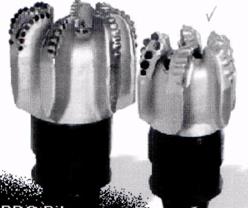
Fig. Various Tri-Cone Bits
For extremely hard formations, a special bit called a PDC is sometimes used. This type of bit has carbide or man-made industrial diamonds set in fixed blades. These blades simply scrape the rock during drilling and do not rotate the way the cones of a tri-cone bit do.
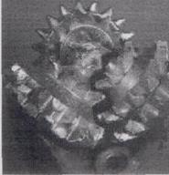 Fig. PDC Bit
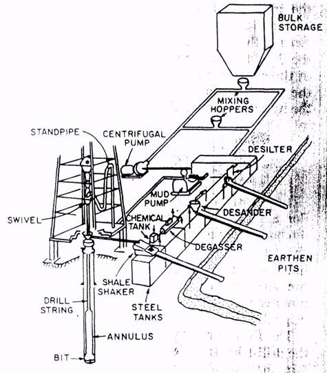
CIRCULATING SYSTEM
Mud circulates through many pieces of equipment, including the mud pump, the discharge line, the standpipe, the rotary hose, the swivel, the kelly (or the top drive), the drill pipe, the drill collars, the drill bit, the annulus, the return line, the shale shaker, the desilter, the desander, the mud pits, and the suction line.
Дата добавления: 2019-01-14; просмотров: 596; Мы поможем в написании вашей работы! |

Мы поможем в написании ваших работ!