How are Geophysical Methods Applied in Practice?
The implementation of geophysical methods is a structured process that consists of a number of key steps, including:
Initial evaluation of the problem at hand (i.e. what is the suspected problem, what initial information is known about the site, what additional information is required, and what are the desired outcomes)
Determination of which geophysical method (or combination of methods) will yield the optimal results. Not all methods will be applicable, therefore, it is critical to carefully assess which methods are most likely to provide data and information relevant to the problem of interest. Also, while some methods may provide information, they may not be cost-effective in a particular context.
Identification of the scope (or size) of the required geophysical coverage.
Assessment of the way in which the data and information are to be acquired, interpreted and presented so as to address the issue at hand.
After these basic questions have been answered and the project approved, the geophysical work will commence.
Incorporated in 1962, Geonics Limited is a world leader in the design, manufacture and service of electromagnetic (EM) geophysical instrumentation.
From a commitment to address the varied, demanding realities of the survey environment, Geonics instrumentation has developed an enduring reputation for practical design and reliable operation, supported by an equal commitment to prompt and comprehensive customer service.
| Instrumentation and software is available in the following product categories: Ground Conductivity Meters: provide (frequency domain) measurement of subsurface conductivity and magnetic susceptibility for spatial site characterization and detection of structural anomalies, both natural (e.g. bedrock fractures) and man-made (e.g. storage tanks). Metal Detectors: for detection of a broad range of subsurface metallic targets, including environmental hazards (e.g. drums, storage tanks), infrastructure, industrial waste, and unexploded ordnance (UXO). Time Domain Systems:provide measurement of vertical subsurface conductivity for definition of the conductivity / resistivity profile and / or detection of geologic anomalies within an exploration range of 5 m (for environmental / engineering applications) to greater than 1000 m (for deep resource exploration). VLF Systems: receive widely broadcast VLF transmissions for reconnaissance detection of structural anomalies (e.g. bedrock fractures, massive sulphides) and / or measurement of local subsurface resistivity. A portable VLF transmitter, for optimal survey design, is also available. Borehole Probes: individually provide measurement of specific soil properties, including conductivity or natural gamma radiation, for an improved understanding of the local subsurface environment; or measurement in the time domain in support of exploration to a borehole depth of 2 kilometres. Data Acquisition Systems: with both hardware and software components, support the collection of data from any Ground Conductivity Meter or Metal Detector; frequency domain-based Borehole Probe are also supported. Software: developed by Geonics Limited, directly supports the collection and processing of data collected with any of the above Data Acquisition Systems. Third Party Software: developed by commercial software parties, directly support the modeling and enhanced processing of data from all Geonics instrumentation. | 
|  EM61-MK2 EM61-MK2  EM63 EM63  EM38-DD EM38-DD  EM31 EM31 
|

|
|
|
Wellbore Seismic
In the early stages of planning exploration and development in a new area, surface seismic surveys are used extensively to delineate prospective structural or stratigraphic traps. When wells are drilled, opportunities exist to improve this situation through the use of well logs.
A more recent geophysical application of wireline logging measurements involves the preparation of a vertical seismic profile (VSP). In this technique, an air gun vibroseis or other seismic source on the surface generates the input signal that is detected by a downhole geophone. As the sound energy travels only once through the weathered surface layers, the resultant profile has much better resolution than the surface seismic around the borehole and can identify reflectors far below the total depth of the well.
Well Seismic Equipment
The equipment consists of a downhole tool with geophones, the CSU surface recording system, offset shooting equipment and an air gun system.
The most commonly used energy source offshore is the air gun. Its safety, reliability, cost, broad spectrum, simple signature and transportability make the air gun a convenient seismic source. The air gun firing chambers may incorporate a wave-shaping kit that significantly reduces the bubble effect and provides a clean signal. The air compressor and air storage bottles provide an adequate air supply for fast, uninterrupted operations. Other sound sources, such as vibroseis units are routinely used in the field depending on specific applications and local conditions.
|
|
|
When using an impulsive source such as an air gun, the source signal is recorded at the surface by a hydrophone. This allows a precise determination of the time break and permits continuous monitoring of the gun signature. The recorded source signature is used to enhance the signals recorded by the geophone in VSP processing.
The data are recorded digitally on magnetic tape with the CSU system. The seismic waveforms can also be stacked to improve the signal-to-noise ratio. The downhole tools currently in use are the Well Seismic Tool (WST), the Seismic Acquisition Tool (SAT) and the Downhole Seismic Array Tool (DSA). The WST tool has four uniaxially stacked geophones that are primarily sensitive to movement in the vertical direction. The SAT tool has three mutually orthogonal geophones for 3-dimensional operation. The DSA tool (Fig. )uses eight sensor packages (shuttles) which are positioned along an insulated multiconductor bridle cable at intervals of up to 50ft. The sensor package contains a vertical geophone for signal acquisition, a magnetic clamping device to secure the package to the casing, a shaker element to generate mechanical vibrations for reference and electronic circuitry to transmit signals to the cartridge. In the cartridge, the signals pass through antialiasing filters, sample- hold circuits and multiplexers and are then digitized and telemetered to the surface. [Fig. 1].
|
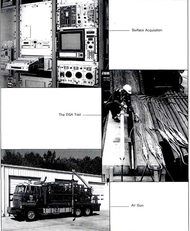
Fig.1 Well seismic tool hardware
|
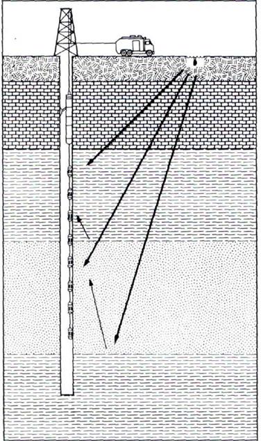
Fig. Schematic of DSA tool in operation
Vertical Seismic Profile
Vertical seismic profiling is a technique of simultaneously recording the upgoing and downgoing wavetrains. This represents a major advantage over the conventional surface reflection seismic technique, which records only the upgoing waves. By recording a sufficient number (50 or more) of fairly regularly spaced levels in the well, the upgoing and downgoing wavefields can be separated by computer processing. An analysis of the upgoing and downgoing components permits the detailed study of the change of the seismic wavetrain with depth. The use of downhole sensors reduces the signal distortion caused by the low-velocity shallow layers since the signal passes only once through the surface layers.
|
|
|
|

Fig. VSP trace contains upgoing and downgoing waves. Multiples can clearly be seen on the display.
The total wavefield recorded at the detector in the borehole consists of signals arriving above the tool ( downgoing) and the signals arriving from below the tool (upgoing). The downgoing signals are the direct (first) arrivals and the downgoing multiples. The upgoing signals consist of the direct reflections and the upgoing multiples.
Advantages of the vertical seismic profile technique include:
- recording a real seismic trace in the borehole rather than relying on a synthetically generated seismogram;
- measuring the spectral content of the downgoing seismic signal as function of depth;
- establishment of a precise link between the surface seismic results and well logs, since the VSP is a high-resolution measurement;
- the recording of signals with an improved high-frequency content, since they cross the highly absorptive low-velocity layers near the surface only once;
- improved seismic resolution of subtle stratigraphic features around the well, such as faults or pinchouts;
- the recording of deep reflector signals that are not received at surface; this is particularly useful in structurally complex areas;
- an excellent record of the band-limited reflection coefficient series through deconvolution of the VSP.
VSP Processing
|
|
|
|

Fig. Processing of VSP’s involves three major steps: data editing for optimized shot quality, upgoing and downgoing wavetrain separation and deconvolution
VSP processing sequence usually includes most of the following steps:
- shot selection by an analyst to reject the noisy, poor-quality shots;
- consistency check of the surface hydrophone signal;
- median stacking of shots;
- check of coherence between a reference level and all others;
- monitoring of phase shifts and acoustic impedance at all levels;
- bandpass filtering to eliminate noise and remove aliased frequencies;
- filtering to help eliminate tube waves;
- true amplitude recovery by a time-variant function to compensate for spherical spreading;
- velocity filtering to separate the upgoing and downgoing components of the total wavefield;
- autocorrelation of the downgoing wave after filtering for selection of the proper deconvolution parameters using the downgoing wave field a a deterministic model;
- predictive deconvolution to remove source signature effects and to improve resolution;
- time-variant filtering to match the surface seismic data;
- corridor stacking: summing all the upgoing waves recorded in a window following the first break.
Дата добавления: 2019-01-14; просмотров: 174; Мы поможем в написании вашей работы! |

Мы поможем в написании ваших работ!