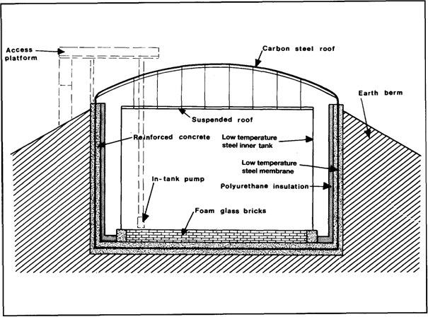
Figure 5.14 Double containment steel tank for LPG

Figure 5.15 LPG tank — earth berm
The mini-bund, as shown in the figure, is provided to contain minor leaks from pipelines, valves and flanges.
A further variation of double containment is shown in Figure 5.15. Here the inner tank is surrounded by a low-temperature steel membrane tank supported by a reinforced concrete wall. This, in turn, is backed with an earth berm to provide further assurance against both internal and external loads. This tank has a steel roof in preference to concrete. These concepts may also be applied to LNG storage tanks.
In-ground storage tanks for LNG
In-ground tanks are a popular option for storing LNG which provide:—
• High-integrity storage with virtually no risk of spillage
• High seismic protection against earthquakes, and
• Minimal visual impact on the environment
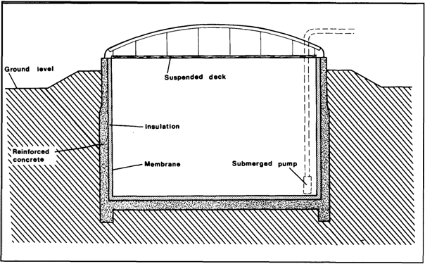
The main features of one such in-ground LNG storage tank are illustrated in Figure 5.16. Primary containment is by a stainless steel membrane, supported (as in ships' membrane-type tanks) by rigid polyurethane foam insulation. This, in turn, is supported within a reinforced concrete caisson. The roof is a dome-shaped carbon steel structure supporting a suspended deck with glass wool insulation (see Reference 2.27).

Figure 5.16 In-ground tank for LMG
5.2.4 Construction materials and design
The material of construction for refrigerated tanks depends on the storage temperature. Carbon steels, or in some cases nickel alloy steels, are utilised for LPG tanks but, for lower temperatures, alternative materials such as nine per cent nickel steel, austenitic stainless steel, Invar or aluminium alloy must be used.
The foundations for all refrigerated tanks, particularly for LNG, require specialised design. This should allow for thermal movements of the tank, anchorage against uplift, insulation of the base and foundation settlement. A further need is to prevent ground freezing and frost heave conditions that may lift and damage the tank. This may be achieved by the provision of an air space under the tank, as in Fig. 5.13. or by the installation of a heating and temperature monitoring system in the foundation and also in the vertical wall of in-ground tanks and tanks with an earth berm.
In all cases, therefore, the involvement of foundation specialists is essential to establish the safe bearing pressures, to design heating systems, to predict anticipated settlements and to oversee soil investigations, including laboratory tests of the foundation material.
|
|
|
With increasing concern for safety and the widespread use of double containment tanks for liquefied gas storage, the use of reinforced or prestressed concrete has grown. Such material is frequently used in the construction of the outer skin of double-wall tanks. In one recently constructed LNG tank, both the inner and outer walls are of prestressed concrete.
Where refrigerated tanks are insulated externally, sealing of the insulation is necessary to prevent moisture ingress-(such as rain) and subsequent freezing. A lack of maintenance, in this respect, has been known to result in insulation collapse.
5.3 ANCILLARY EQUIPMENT
5.3.1 Pressure relief venting
Liquefied gas tanks must be fitted with pressure relief valves. In certain designs, for example in the case of refrigerated tanks, vacuum breakers are also fitted. These protect the tank against pressure excursions due to process malfunction or fire conditions. Both conventional spring-loaded and pilot-operated pressure relief valves are used, as described in Chapter Four. Relief can take place either to atmosphere or to a flare. This will depend on storage quantities, site layout and products handled. Flame arresters in vent lines are a potential cause of blockage (with consequent tank failure) and, accordingly, they must be regularly inspected and maintained.
Tankage is usually provided with a water deluge system to give additional protection in the event of fire. Alternatively, thick tumescent coatings, which char in fire conditions giving substantial heat absorption and insulation, are being increasingly used.
5.3.2 Pipelines and valves
Pipelines and valves used in liquefied gas service are designed, installed and maintained in accordance with the appropriate standards and codes of practice. This means, for example, provision for positive isolation at inlet and outlet of all storage vessels, adequate allowance for thermal expansion and contraction in pipelines and pressure relief for liquid trapped between isolation valves. Sample points are normally provided with double shut-off valves. It is customary to open the primary isolation valve fully and throttle on the second valve. In this way any blockage due to hydrate formation will occur at the second valve, leaving the primary valve free to isolate again while the blockage is cleared. This is of particular importance for drainage connections of pressure vessels.
|
|
|
Дата добавления: 2018-02-28; просмотров: 567; Мы поможем в написании вашей работы! |

Мы поможем в написании ваших работ!
